Tag Archives: Instructions

DMR In Amateur Radio: Programming a Code Plug

Read the rest of the series in the DMR in Amateur Radio series category.


You picked up a new DMR radio! Congratulations! You maybe thinking, what have I gotten myself into? Good question. DMR is the first commercial mode adopted for ham radio use. Terminology and radio setup are familiar to those who program commercial gear. If you’re coming across this programming example and have not read the first part on terminology, please do so as this will build upon it. Passing around a code plug makes DMR seem plug-and-play and it’s a great way to get started. Doing so tends to leave most of us unable to change the configuration of our own radios. My goal is to demonstrate how to program a DMR ham radio code plug from scratch. This will lead to understanding how code plugs work and how to modify them. I will demonstrate programming a code plug for an example repeater, hotspot, and simplex operation.

In addition to this example, I recommend looking at available code plugs online to get an idea of different ways to improve yours. This is how I learned to program code plugs. There is no central database or repository. Code plugs are scattered around the Internet and shared online. This makes sense because local users would know where to get a code plug. Ask others in the area with similar DMR radios where to find code plugs. The ARRL Ohio site has ones for Ohio’s DMR repeaters: http://arrl-ohio.org/digital/digital.html. Where this works for local hams, a scavenger hunt is required to find working code plugs for an area they’re visiting.

Screen shots and settings referenced in this tutorial are from the TYT MD-380 CPS and radio. Similar settings can be found in other programmers and radios. Functions of not-so-obvious radio settings are described in the appropriate sections.

Software (TYT & Connect Systems)

Updating settings and memories in all DMR radios requires a computer, programming cable, and CPS. Check radio packaging because some include the cable and software, others consider it an additional accessory. Most stock CPSes can’t rearrange entries or import from other sources. If you entered a new contact and wanted to rearrange the order, you can’t. If you want to import thousands of users, you can’t. Third-party code plug editors provide this additional functionality. All are freeware.

Tytera (TYT) MD-380/390/2017 CPS and firmware: http://www.tyt888.com/?mod=download

Connect Systems documentation, CPS, and firmware: http://www.connectsystems.com/software/

MD380 Tools: https://github.com/travisgoodspeed/md380tools
Alternative firmware for the TYT MD-380. Use at your own risk.

TYT MD-380 / 390 Code Plug Editor: http://www.miklor.com/DMR/DMR-380-CPEditor.php
Editor for importing/exporting settings, importing from the DMR-MARC user database, and rearranging entries. The TYT CPS is still needed to write the code plug to the radio. This is my preferred MD-380 editor.

N0GSG’s DMR Contact Manager: http://n0gsg.com/contact-manager/
Works for most models of Connect Systems, Tytera, Retevis, and AnyTone radios. Editor can import/export settings and import contacts from the DMR-MARC user database, comma separated file (CSV), or existing code plug. Sorting is accomplished by clicking the header columns. Radio CPS is still needed to write the code plug to the radio.

The last three are free to use but please consider a donation to the developer if you find their work useful.

Radio ID, general settings, and FPP

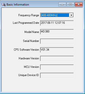
After installing the CPS, in “Basic Information,” first check the “Frequency Range” is correct for the radio.

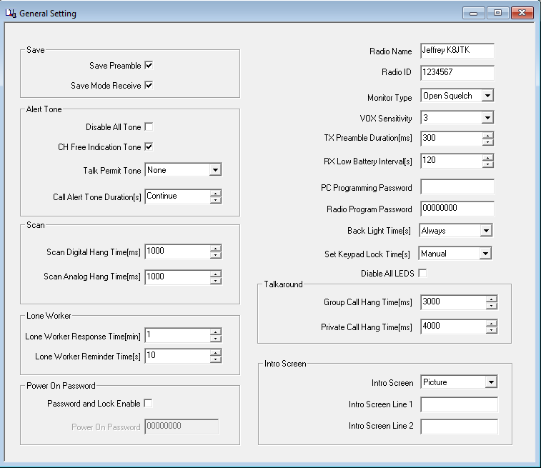
First thing to program is your “Radio ID.” You registered for one, right? It is found in the CPS under “General Settings.” Enter your assigned CCS7 ID. When passing around a code plug or loading someone else’s, update the CCS7 ID otherwise you will appear as someone else.

The “Radio Name” can be whatever name you want to give the radio.

I like to have a notification when the transmission is complete and the channel is free. This is known as the ‘CH Free Indication Tone.’ NOTE: this tone did not work with the DV4Mini for some reason.

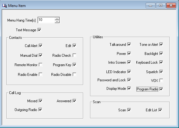
Enable FPP so the programming can be modified from the radio’s keypad. Remember to read the radio or update changes made through FPP into the CPS. Changes will be overwritten when the code plug is downloaded again to the radio. In the CPS, FPP can be enabled in “Menu Item,” under “Utilities,” check “Program Radio.”

To enter FPP mode on the radio, go to the menu, select “Settings,” and “Program Radio.” The “Radio Program Password” in “General Settings” of the CPS is used when entering FPP on the radio. This is a commercial carryover to keep users from screwing with the radio. Enter the program password, if needed, and voila.

Hang-time, delays, and other adjustments can be made and experimented with at your leisure.

Programming example

In order to successfully program a code plug for a repeater, Color Code, talk group, and time slot configuration must be known. This information can be obtained from RepeaterBook, RFinder, owner/club website, asking another user or the repeater owner. Also ask if the repeater has access to reflectors, if desired. Brandmeister and DMR-MARC repeaters have reflector access.

A configuration example of a factitious repeater is outlined below. I’ve picked common U.S. talk groups for each time slot and will use the “Area 8” reflector as examples. When you become more comfortable, substitute the local repeater’s information.

Private calls to individuals are never a mandatory part of repeater configuration. They are possible and will be shown as an example. I include private call channels for frequent contacts as part of my hotspot code plug.

The “type” column in the table below is for informational/clarification purposes only and would not necessarily be provided by the owner (see the previous terminology write-up).

Labeling and organization of the code plug is user preference. RX Group lists and channels will need an abbreviation or prefix noting to which system it applies. When programming even 10 repeaters, some distinction must be made for clarity. Prefixes help programming because similar items are grouped together in the CPS. Rationale behind this will become clearer as you add repeaters to a code plug. Some might like to have the city spelled out (Cleveland, Dayton, Columbus, Cincinnati, Toledo) while having the talk groups abbreviated (WW, NA, Lcl 9, TAC-311, Statewide). Others like to have the city abbreviated (Cle, Day, Col, Cin, Tol) while the talk group is spelled out (World-Wide, North America, Local 9, TAC-311, Ohio). No two items may have the same exact name in any one area: Contacts, RX Groups, Channels, Zones, or Scan Lists. “SC” will be the prefix used for this example to indicate “Some City.”

Call: K8XXX City: Some City, OH Output: 444.300
Input: 449.300
Color Code: 1
Label Type ID Time Slot
World-Wide Talk group 91 1
North America Talk group 93 1
USA – Nationwide Talk group 3100 1
Local 9 (or Reflector) Talk group 9 2
TAC-310 Talk group 310 2
TAC-311 Talk group 311 2
TAC-312 Talk group 312 2
Midwest (regional) Talk group 3169 2
Ohio (statewide) Talk group 3139 2
USA – Area 8 Talk group 4648 2

Individual contact

Scott N8SY User 3139437 N/A

Contacts

Digital contacts are required to be setup first. These drives the ability to build RX Lists and channels. Every talk group, reflector, or user gets a contact. Relevant information in the table above: Label, Type, and ID.

It’s best to follow the labeling/naming provided by the c-Bridge. Some radios don’t have a lot of display real estate and names must be shortened to something like “WW” for talk group 91, “NA” for 93.

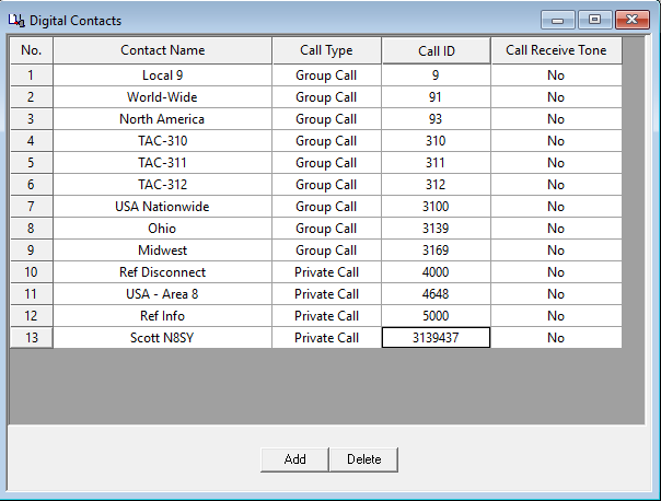
There are four fields per “Digital Contact” record in the CPS:

  • Contact Name
  • Call Type
  • Call ID
  • Call Receive Tone

“Contact Name” is simply the name you give each contact and is the label seen on the radio while receiving a call from that ID. “Call Type” is group/private/all-call setting. “Group” is for talk groups and “Private” is used for radio-to-radio calls or commands. “Call ID” is the numeric talk group, reflector, radio ID, or command number. “Receive Tone” is a per-call setting where a tone is emitted from the radio prior to unmuting the audio. This can be used as notification prior to receiving a call from a contact of interest.

There cannot be two contacts with the same “Call ID” or the same “Contact Name.” When programming different repeaters, potentially on different networks, all talk groups for all c-Bridges are entered as contacts. If two networks label talk group 3333 differently, a generic display name will have to be chosen, such as “3333” or “Group 3333.” On the other hand, “Example talk group” is talk group ID 3333 on one network and ID 3344 on another, then two differently named contacts have to be created for the same talk group (ie: “ExTG 3333” with ID 3333, “ExTG 3344” with ID 3344).

If the repeater owner says they follow K4USD’s talk group layout for example, they have nearly 70 available talk groups on their c-Bridge. Though it seems like a lot of work at the time, I recommend creating contacts for all 70 available talk groups. Having all talk groups programmed will result in less effort changing the code plug later. Brandmeister on the other hand, good luck. You really have to decide which talk groups are of interest because all talk groups are available to all repeaters and hotspots. To keeps things simple, stick with the repeater owner’s suggested Brandmeister groups.

For this programming example, contacts are pre-sorted by ID number. In the CPS software, create Digital Contacts with the listed settings:

  • Contact #1
    • Contact name: Local 9
    • Call type: Group call
    • Call ID: 9
    • Receive tone: No
  • Contact #2
    • Contact name: World-Wide
    • Call type: Group call
    • Call ID: 91
    • Receive tone: No
  • Contact #3
    • Contact name: North America
    • Call type: Group call
    • Call ID: 93
    • Receive tone: No
  • Contact #4
    • Contact name: TAC-310
    • Call type: Group call
    • Call ID: 310
    • Receive tone: No
  • Contact #5
    • Contact name: TAC-311
    • Call type: Group call
    • Call ID: 311
    • Receive tone: No
  • Contact #6
    • Contact name: TAC-312
    • Call type: Group call
    • Call ID: 312
    • Receive tone: No
  • Contact #7
    • Contact name: USA Nationwide
    • Call type: Group call
    • Call ID: 3100
    • Receive tone: No
  • Contact #8
    • Contact name: Ohio
    • Call type: Group call
    • Call ID: 3139
    • Receive tone: No
  • Contact #9
    • Contact name: Midwest
    • Call type: Group call
    • Call ID: 3169
    • Receive tone: No
  • Contact #10
    • Contact name: Ref Disconnect
    • Call type: Private call
    • Call ID: 4000
    • Receive tone: No
  • Contact #11
    • Contact name: USA – Area 8
    • Call type: Private call
    • Call ID: 4648
    • Receive tone: No
  • Contact #12
    • Contact name: Ref Info
    • Call type: Private call
    • Call ID: 5000
    • Receive tone: No
  • Contact #13
    • Contact name: Scott N8SY
    • Call type: Private call
    • Call ID: 3139437
    • Receive tone: No

Notice contacts #10 and #12 are not listed in the example table. These are standard reflector commands. A private call to ID 4000 is required to disconnect the repeater, 5000 checks link status. Talk group 9 is also required for reflector use. See the Reflector section for usage.

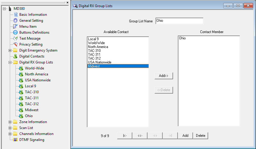
(Digital) RX Group lists

Once Contacts are entered, RX Group lists can be created. Relevant information from the example table: Label and Time Slot. RX Group lists are limited to a maximum of 32 talk groups per list. The intent was to monitor all talk group activity on a time slot. Only contacts set to “Group Call” can be added.

There are generally two ways of creating RX Groups. The first uses a one-to-one relationship where each talk group has its own RX Group List. The second includes all available talk groups on a repeater’s time slot into a single list. The latter creates lists unique to a repeater that cannot be reused on another repeater, unless the configuration is exactly the same. If the repeater has less than 32 talk groups on a time slot, put them all in one RX Group list. If there are more than 32, then create one RX list per talk group.

To keep repeater specific group lists unique, name the list: repeater location followed by “TS1/2” for the time slot designation. Example: “Some City TS1,” “Some City TS2.”

RX Group lists and the RX list selected for a channel are the first places to look when there is a suspected radio programming issue or nothing is being heard.

A repeater specific example is provided later. For this programming example, the one-to-one relationship is demonstrated. RX Groups are created in the same order as the repeater listing. In the CPS software, create RX Group lists and include the listed contact(s):

  • Digital RX Group List #1
    • Group List Name: World-Wide
    • Available Contact, select and add: World-Wide
  • Digital RX Group List #2
    • Group List Name: North America
    • Available Contact, select and add: North America
  • Digital RX Group List #3
    • Group List Name: USA Nationwide
    • Available Contact, select and add: USA Nationwide
  • Digital RX Group List #4
    • Group List Name: Local 9
    • Available Contact, select and add: Local 9
  • Digital RX Group List #5
    • Group List Name: TAC-310
    • Available Contact, select and add: TAC-310
  • Digital RX Group List #6
    • Group List Name: TAC-311
    • Available Contact, select and add: TAC-311
  • Digital RX Group List #7
    • Group List Name: TAC-312
    • Available Contact, select and add: TAC-312
  • Digital RX Group List #8
    • Group List Name: Midwest
    • Available Contact, select and add: Midwest
  • Digital RX Group List #9
    • Group List Name: Ohio
    • Available Contact, select and add: Ohio

Notice contacts #10-13 cannot be included because they are set to private call.


Repeater specific, all talk groups per time slot example:

  • Digital RX Group List #1
    • Group List Name: Some City TS1
    • Available Contact, select and add (position 1): World-Wide
    • Available Contact, select and add (position 2): North America
    • Available Contact, select and add (position 3): USA Nationwide
  • Digital RX Group List #2
    • Group List Name: Some City TS2
    • Available Contact, select and add (position 1): Local 9
    • Available Contact, select and add (position 2): TAC-310
    • Available Contact, select and add (position 3): TAC-311
    • Available Contact, select and add (position 4): TAC-312
    • Available Contact, select and add (position 5): Midwest
    • Available Contact, select and add (position 6): Ohio

Channels

This is where it all comes together. To create channels, Contacts and RX Group lists need to have been established.

Analog channels are straight forward if you’ve programmed any other analog ham radio. They will not be covered here.

Channels for the same repeater are easier to copy and paste. This depends on the software but usually involves setting up a channel, copying that channel, creating a blank channel, and pasting over the blank channel.

Some settings definitions:

  • Admit Criteria: determines when the radio is allowed to transmit.
    • Always: allows the radio to transmit any time PTT is pressed. This is the most disruptive option and may interrupt another QSO in progress.
    • Channel Free: the radio will only transmit when there is no transmission in progress on the time slot.
    • Color Code (Free): the radio will only transmit when the time slot is free on the repeater matching the color code. This mode pings the repeater at the beginning of each transmission to find a matching color code. This pinging is also an indicator if you’re making the repeater or if it is in use.
    • “Color Code” is recommended for a repeater, “Channel Free” for hotspot & simplex use.
  • In Call Criteria: action taken while receiving a call and the PTT button is pressed. This can be thought of as the ‘interrupt a call’ setting.
    • Follow Admit Criteria: follow the setting defined in “Admit Criteria.”
    • Always: always transmit, even while receiving a call.
    • “Follow Admit Criteria” is recommended for a repeater, “Always” for hotspot & simplex use.
  • Auto Scan: when the channel is selected, the radio begins scanning channels defined in the selected “Scan List.” For this option to function: create channels, add the channels to a Scan List, then create another new channel with the newly created Scan List selected and “Auto Scan” checked.
  • Lone Worker: the user receives an alert from the radio after a specified amount of time and must acknowledge by pressing any button on the radio. If the user does not respond to the alert, it is assumed the user is injured or incapacitated. The radio switches to an emergency mode so the user can be located and assisted. I have not seen this used in ham radio.
  • Allow Talkaround: this allows the radio to operate simplex mode when a repeater is not available or out-of-range. TX and RX frequencies must be different for this option to function. Talkaround is enabled/disabled manually via the radio’s “Utilities” menu, select “Radio Settings,” select “Talkaround,” then select “Turn On/Off.”
  • Emergency System: settings for an emergency alarm. I have not seen this used in ham radio.
  • Privacy: DMR includes the ability to “scramble” transmissions. This is a form of encryption and not allowed in the US.

A clear definition of “RX/TX Ref Frequency” has not been found and understood the default setting is sufficient.

Provided by Rich – G3ZIY:

These two drop-down selections are provided to change the radio’s basic oscillator frequency in the receive or transmit side. Because the radio covers such a wide frequency range, on some specific receive or transmit frequencies there can be a birdie generated internally which interferes with reception or transmission. If this occurs, by simply trying a different setting from the current setting, it should be possible to get clear reception and a clean transmission.

Leave “TX/RX Ref Frequency” at the default unless you experience problems transmitting or receiving and tack the problem down to the radio itself.

These settings will be applied to every digital channel created for this example and is a good template for actual programming:

  • Channel Mode: Digital
  • Band Width: 12.5kHz
  • TOT[s]: 180s (3 min) max for repeater & hotspot, 600s (10 min) max for simplex channels.
  • Power: “High” for repeaters & simplex – unless really close, “Low” for hotspots.
  • Admit Criteria: “Color Code” for repeater, “Channel Free” for hotspot & simplex.
  • Allow Talkaround: yes
  • Emergency System: None
  • Privacy: None
  • In Call Criteria: “Follow Admit Criteria” for repeater, “Always” for hotspot & simplex.

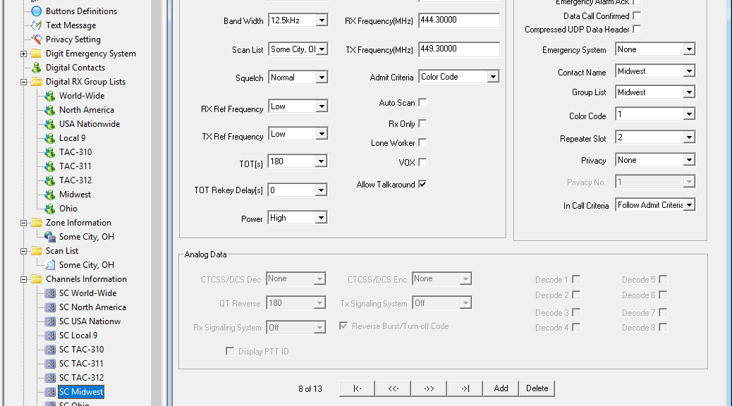
For this programming example, channels are created in the same order as the repeater listing. In the CPS software, create channels with the listed settings including universal settings above. SC = Some City, Ohio:
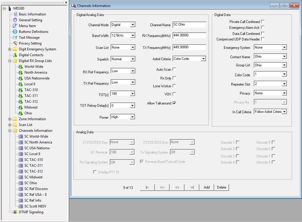
  • Channel #1
    • Channel Name: SC World-Wide
    • RX Frequency: 444.300
    • TX Frequency: 449.300
    • Contact Name: World-Wide
    • Group List: World-Wide (or Some City TS1)
    • Color Code: 1
    • Repeater Slot: 1
  • Channel #2
    • Channel Name: SC North America
    • RX Frequency: 444.300
    • TX Frequency: 449.300
    • Contact Name: North America
    • Group List: North America (or Some City TS1)
    • Color Code: 1
    • Repeater Slot: 1
  • Channel #3
    • Channel Name: SC USA Nationw
    • RX Frequency: 444.300
    • TX Frequency: 449.300
    • Contact Name: USA Nationwide
    • Group List: USA Nationwide (or Some City TS1)
    • Color Code: 1
    • Repeater Slot: 1
  • Channel #4
    • Channel Name: SC Local 9
    • RX Frequency: 444.300
    • TX Frequency: 449.300
    • Contact Name: Local 9
    • Group List: Local 9 (or Some City TS2)
    • Color Code: 1
    • Repeater Slot: 2
  • Channel #5
    • Channel Name: SC TAC-310
    • RX Frequency: 444.300
    • TX Frequency: 449.300
    • Contact Name: TAC-310
    • Group List: TAC-310 (or Some City TS2)
    • Color Code: 1
    • Repeater Slot: 2
  • Channel #6
    • Channel Name: SC TAC-311
    • RX Frequency: 444.300
    • TX Frequency: 449.300
    • Contact Name: TAC-311
    • Group List: TAC-311 (or Some City TS2)
    • Color Code: 1
    • Repeater Slot: 2
  • Channel #7
    • Channel Name: SC TAC-312
    • RX Frequency: 444.300
    • TX Frequency: 449.300
    • Contact Name: TAC-312
    • Group List: TAC-312 (or Some City TS2)
    • Color Code: 1
    • Repeater Slot: 2
  • Channel #8
    • Channel Name: SC Midwest
    • RX Frequency: 444.300
    • TX Frequency: 449.300
    • Contact Name: Midwest
    • Group List: Midwest (or Some City TS2)
    • Color Code: 1
    • Repeater Slot: 2
  • Channel #9
    • Channel Name: SC Ohio
    • RX Frequency: 444.300
    • TX Frequency: 449.300
    • Contact Name: Ohio
    • Group List: Ohio (or Some City TS2)
    • Color Code: 1
    • Repeater Slot: 2
  • Channel #10
    • Channel Name: SC Ref Disconn
    • RX Frequency: 444.300
    • TX Frequency: 449.300
    • Contact Name: Ref Disconnect
    • Group List: None
    • Color Code: 1
    • Repeater Slot: 2
  • Channel #11
    • Channel Name: SC Ref USA – 8
    • RX Frequency: 444.300
    • TX Frequency: 449.300
    • Contact Name: USA – Area 8
    • Group List: None
    • Color Code: 1
    • Repeater Slot: 2
  • Channel #12
    • Channel Name: SC Ref Info
    • RX Frequency: 444.300
    • TX Frequency: 449.300
    • Contact Name: Ref Info
    • Group List: None
    • Color Code: 1
    • Repeater Slot: 2
  • Channel #13
    • Channel Name: SC Scott N8SY
    • RX Frequency: 444.300
    • TX Frequency: 449.300
    • Contact Name: Scott N8SY
    • Group List: None
    • Color Code: 1
    • Repeater Slot: 2 – though really depends which is available on the repeater.

Zones

To use a Channel on the radio, it needs to be added to a Zone. Zones can contain analog channels too.

Some repeater and c-Bridge owners only made 16 talk groups available on their systems. That’s easy. All 16 go into one zone. Repeaters with more than 16 talk groups must have channels grouped.

Order of channels added to a zone will correspond with the dial position: first added will be position 1, second added will be 2, and so on.

Most use the zone to indicate where the repeater is located. Call signs are not often used because the city provides more detail when selecting an appropriate zone, especially when traveling.

For this programming example, only one zone is utilized. In the CPS software, create a zone with the listed channels:
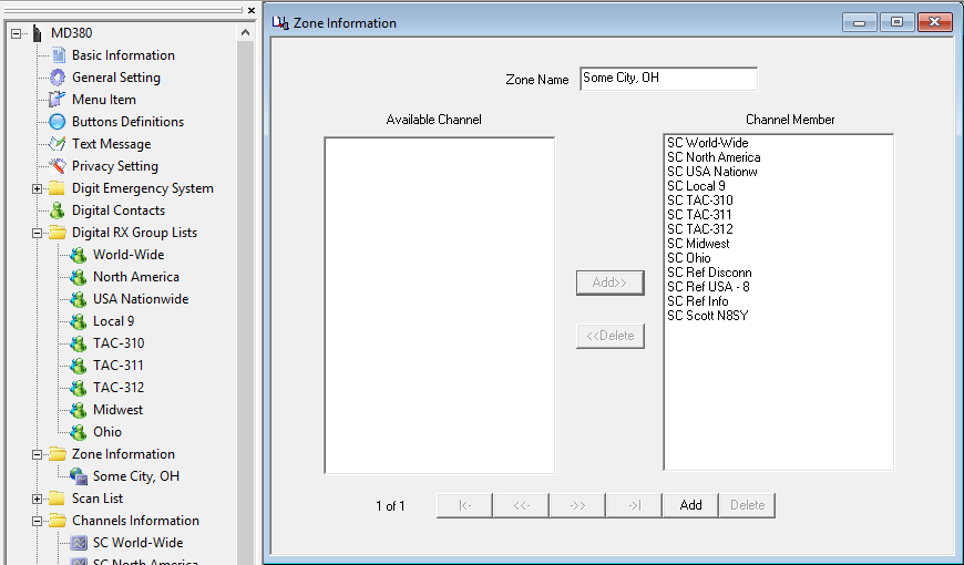
  • Zone Information #1
    • Zone Name: Some City, OH
    • Available Channel, select and add (position 1): SC World-Wide
    • Available Channel, select and add (position 2): SC North America
    • Available Channel, select and add (position 3): SC USA Nationw
    • Available Channel, select and add (position 4): SC Local 9
    • Available Channel, select and add (position 5): SC TAC-310
    • Available Channel, select and add (position 6): SC TAC-311
    • Available Channel, select and add (position 7): SC TAC-312
    • Available Channel, select and add (position 8): SC Midwest
    • Available Channel, select and add (position 9): SC Ohio
    • Available Channel, select and add (position 10): SC Ref Disconn
    • Available Channel, select and add (position 11): SC Ref USA – 8
    • Available Channel, select and add (position 12): SC Ref Status
    • Available Channel, select and add (position 13): SC Scott N8SY

Scan Lists

Scan Lists are not required for radio operation but are nice for scanner like functionality across repeater time slots and frequencies. Channels have to be established first before it can be added. Scan Lists can contain analog channels too.

Order of channels added to a Scan List will correspond with the scan order. Private Call channels are unnecessary in scan lists because they are infrequent, short, and unnecessarily take up available list entries.

Activating the selected Scan List on the active channel requires assigning the “Scan On/Off” functionality to a programmable button universally in the radio. This is done in “Button Definitions” of the CPS. Another way is to create a channel with the “Auto Scan” feature enabled (see Channels section).

For this programming example, only one Scan List is utilized. In the CPS software, create a Scan List with the listed channels:
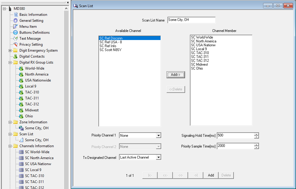
  • Scan List #1
    • Scan List name: Some City, OH
    • Available Channel, select and add (position 1): SC World-Wide
    • Available Channel, select and add (position 2): SC North America
    • Available Channel, select and add (position 3): SC USA Nationw
    • Available Channel, select and add (position 4): SC Local 9
    • Available Channel, select and add (position 5): SC TAC-310
    • Available Channel, select and add (position 6): SC TAC-311
    • Available Channel, select and add (position 7): SC TAC-312
    • Available Channel, select and add (position 8): SC Midwest
    • Available Channel, select and add (position 9): SC Ohio

Once a Scan List is created, Channels to which a Scan List applies must be updated. All of the “SC” channels.


That’s it! You have successfully programmed a ham radio DMR code plug from scratch! Now, substitute the local repeater’s information and begin having fun!

Suggested talk groups

Here is a suggested list of talk groups to get started on a Brandmeister network U.S. repeater or hotspot. Each bullet can be a separate zone.

  • Wide area groups (World-Wide: 91, North America: 93, USA – Nationwide: 3100)
  • Regional (Midwest: 3169, Southern Plains: 3175, Northeast: 3172, Mountain: 3177, etc.)
  • Ohio & surrounding states (Ohio: 3139, Indiana: 3118, Michigan: 3126, Pennsylvania: 3142, West Virginia: 3154, Kentucky: 3121)
  • Local & tactical (TAC) (1, 2, Local 9, TAC-310, TAC-311, TAC-312, TAC 1: 8951, TAC 2: 8952, …, TAC 9: 8959)
  • Reflectors & commands (Disconnect: 4000, USA – Nationwide: 4639, USA – Area 0: 4640, USA Area 1: 4641, …, USA – Area 9: 4649, Ref Info: 5000)
  • Special use (Parrot: 9990, audio test: 9999)

Reflectors

Update 2/2021: Brandmeister has dropped reflector support at the end of 2020.  This information would still be applicable to other networks that use reflectors.

Reflectors are different than talk groups. With a talk group, keying automatically establishes the connection and is dropped after 15 minutes. Reflectors must be manually linked and unlinked. Time slot 2 is always used for reflectors and associated commands.

At user discretion, programming can include reflectors of interest. It’s a good idea to program the control commands into a code plug regardless of the desire to use reflectors. A repeater maybe connected to a reflector and left abandoned. Having those commands programmed are good for knocking down an abandoned link.

To establish reflector connection, a private call is made to the reflector ID. Some radios can make on-the-fly private calls by entering the ID on the keypad. Others need a channel programmed with the reflector ID in the “Call ID” field with “Call Type” set to “Private Call.”

A “Group Call” channel programmed to time slot 2, talk group 9 is required to carry on the QSO. This is known as “Local 9” on many repeaters.

When the QSO is finished, another “Private Call” is made to ID 4000 to disconnect the reflector. Private Call to ID 5000 will check the status at any time.

For two stations to establish communication on the “USA – Area 8” reflector (4648), both stations initiate a “Private Call” to ID 4648 on time slot 2, for 2 seconds. Switch their radios to “Local 9” for the QSO. When done, both initiate a private call to 4000 to disconnect their nodes.

Simplex

Like any good communication system, DMR doesn’t have to be operated using a repeater.

Standard DMR simplex configuration and frequencies in the U.S.:

  • Talk group (contact ID and RX Group): 99
  • Color Code (channel): 1
  • Time slot (channel): 1
  • Admit Criteria (channel): Always (though I like to use “Channel Free”).
  • In Call Criteria (if applicable, channel): TX or Always.
  • UHF
    • 441.000
    • 446.500
    • 446.075
    • 433.450
  • VHF
    • 145.790
    • 145.510


Simplex code plug programming template:

  • Contact
    • Contact name: Simplex
    • Call type: Group call
    • Call ID: 99
    • Receive tone: No
  • Digital RX Group List
    • Group List Name: Simplex
    • Available Contact, select and add: Simplex
  • Channel, common:
    • Channel Mode: Digital
    • Band Width: 12.5kHz
    • TOT[s]: 600s (10 min) max.
    • Power: High
    • Admit Criteria: Always
    • Allow Talkaround: yes
    • Emergency System: None
    • Privacy: None
    • In Call Criteria: Always
    • Contact Name: Simplex
    • Group List: Simplex
    • Color Code: 1
    • Repeater Slot: 1
  • Channel 1
    • Channel Name: Simplex 441.000
    • RX Frequency: 441.000
    • TX Frequency: 441.000
  • Channel 2
    • Channel Name: Simplex 446.500
    • RX Frequency: 446.500
    • TX Frequency: 446.500
  • Channel 3
    • Channel Name: Simplex 446.075
    • RX Frequency: 446.075
    • TX Frequency: 446.075
  • Channel 4
    • Channel Name: Simplex 433.450
    • RX Frequency: 433.450
    • TX Frequency: 433.450

Hotspots

Many hotspots follow very similar programming to that of a repeater. Others offer a ‘simple’ mode utilizing a single talk group in the radio to make programming easier. I prefer my hotspot to function like a repeater.

Hotspot devices like the SharkRF OpenSpot and DVMega act similar to a repeater in terms of the programming. Follow the programming tutorial above with differences being the TX frequency would match the RX frequency (simplex) and time slot is always 2 (though the OpenSpot can use either).

For the OpenSpot, every RX Group will need to include “Local 9” to hear the voice announcements from the OpenSpot. These are the ‘connected’ and ‘profile’ announcements. There are additional control commands that can be used with the OpenSpot, like changing profiles, which are outlined in the manual: https://www.sharkrf.com/products/openspot/manual/

The OpenSpot can alternatively operate in a simple mode where transmissions to and from the Internet are routed to and from talk group 9 for the radio. Example: hotspot is connected to talk group 3139, the radio receives and transmits using talk group 9; connected to talk group 3100, radio still uses 9. Using this method, talk group changes have to be made through the OpenSpot web interface including changing the ‘Reroute ID.’

The DV4Mini will ONLY operate using talk group 9. For this reason, programming talk group 3139 into the radio for the DV4Mini will NOT work. No other talk group configuration will work with the DV4Mini EXCEPT talk group 9!

Brandmeister Extended Routing (XTG) is needed for talk groups not listed in the DV4Mini DV4MF2 application (eg: TAC-310, TAC-311, or TAC-312).

A programming example for OpenSpot in ‘simple’ mode or the DV4Mini. 446.900 is the simplex frequency chosen for the hotspot:

  • Contact (does not need to be created if “Local 9” already exits.)
    • Contact name: OpenSpot/DV4Mini
    • Call type: Group call
    • Call ID: 9
    • Receive tone: No
  • Digital RX Group List (does not need to be created if “Local 9” already exits.)
    • Group List Name: OpenSpot/DV4Mini
    • Available Contact, select and add: OpenSpot/DV4Mini
  • Channel
    • Channel Mode: Digital
    • Band Width: 12.5kHz
    • TOT[s]: 180s (3 min) max.
    • Power: Low
    • Admit Criteria: Always (though I like to use “Channel Free”).
    • Allow Talkaround: yes
    • Emergency System: None
    • Privacy: None
    • In Call Criteria: Always
    • Channel Name: OpenSpot/DV4Mini
    • RX Frequency: 446.900
    • TX Frequency: 446.900
    • Contact Name: OpenSpot/DV4Mini (or Local 9)
    • Group List: OpenSpot/DV4Mini (or Local 9)
    • Color Code: 1
    • Repeater Slot: 2

You’re now setup to use OpenSpot in simple mode or DV4Mini!

APRS RX IGate with RTL-SDR and Raspberry Pi

For sometime I wanted to experiment with an APRS IGate. Coverage was spotty at best in my area. There is an IGate in my city but it doesn’t receive so well. Recently there have been more IGates blanketing the area.

APRS stands for Automatic Packet Reporting System and has been developed since the late 1980s by Bob Bruninga – WB4APR. It’s a digital communication mode amateur radio operators use to primarily broadcast location information, though this wasn’t the intended use. It handles text messages, alerts, announcements, bulletins, and information of interest like weather station reports. APRS operates typically on a single frequency.  A system of relay stations and digipeaters repeat messages over a wide area. APRS Internet System (APRS-IS) are Internet connected receivers (IGates).

Any ham can add an icon or information to the APRS map.  The information is available on the Internet or to users on the local RF network.  Data is automatically tracked over time. APRS is frequently used to track mobile stations in a public service event or volunteers in a search and rescue event to visualize locations and track progress.

This project will utilize the Raspberry Pi and RTL-SDR dongle. The Raspberry Pi is a credit-card sized micro-computer intended for teaching computer science to students but became popular with the makers. RTL-SDR dongles are DVB-T (European standard) TV tuner dongles. It was found the signal data could be accessed directly which allowed them to be converted into wide band software defined radio receivers. The Pi costs about $35 and RTL-SDR about $20.

Since the RTL-SDR dongles are meant to receive high power wide bandwidth TV signals, they are not as as sensitive or frequency stable as a ham radio or scanner. Receiver performance will be a little less than an equivalent radio performing the same task but depends on the usual variables: amount of APRS activity, antenna height, antenna gain, propagation, etc, etc. With my antenna about 15 feet high, I get about 5+ miles of coverage. With band openings I’ve heard stations on the opposite side of town and across Lake Erie into Canada.

Even though this IGate will be non-transmitting (cannot relay packets from the Internet), packets are forwarded to APRS-IS. The higher profile – higher power Digitpeaters in the area will relay packets received by your IGate to the local RF network.

Assumptions

This guide is step-by-step in nature, meant for beginners, with brief explanations of the steps. It will help to have an understanding of Linux commands and scripting. Capitalization is important in Linux!

My setup is on my home LAN. The IGate could be installed at a remote site using a shared Internet connection. Be aware that firewalls that might block connection to the APRS-IS network on a shared connection. You may want to request or have port 22 open on your router for SSH to establish a remote connection.

If all wired options fall through, look for a cellular hotspot device such as a MiFi to install along with the Pi. Use the built in WiFi on the Pi 3 or approved WiFi dongles for earlier Pi devices. Associate the MiFi with your Pi (turning on WPA2 so no one else piggybacks on your connection). Test the setup before installing it. Don’t find out after leaving the site that the MiFi times out after a few hours.

Program versions

Applications and versions used in this writeup:

  • Windows 10 64 bit
  • Raspbian Jessie 2016-05-27
  • Win32 Disk Imager 0.9.5
  • PuTTY 0.67
  • SDR Sharp 1.0.0.1444
  • RTL-SDR 0.5.3
  • Multimon-NG ?
  • Pymultimonaprs 1.3.0

Parts list

Listed below are all the parts needed to get this project working. It is noted when items can be left out or substituted.

That’s all the parts needed for this project. Check out the AdaFruit Raspberry Pi page for other hardware that might be useful, like the USB to PS/2 adapter for example. Many of these parts are included in the Raspberry Pi Starter Pack.

Use Soundcard Oscilloscope to understand DSP features of an HF radio

As I continue to use Soundcard Oscilloscope in the shack, I find new uses for it.  In a previous post, I showed how to use it to calibrate receive levels for Ham Radio digital modes.  I’ve used Soundcard Oscilloscope to understand DSP (Digital Signal Processing) features of my radio.  I have an ICOM IC-7000 which doesn’t have any of the features the newer/larger radios: waterfall display, frequency display, or oscilloscope.  As a substitute, I’ll fire up Soundcard Oscilloscope to set filters eliminating loud adjacent stations or set a manual notch filter for annoying stations that tune up on frequency.

Soundcard Oscilloscope is a program that emulates an oscilloscope from signal data received from a sound card. It also has a frequency graph which will be used for this tutorial.

Station setup

  • HF Radio and antenna.
  • SignaLink USB and correct cable for your radio (pictures).  Any audio interface will work or even 1/8″ male-to-male audio cable between the audio out of the radio and Line-in on any regular sound card.
  • PC computer where the radio interface is connected.

Program versions

  • Windows 7 – 64 bit
  • Soundcard Oscilloscope 1.46

Download and Installation

This will install Soundcard Oscilloscope on your PC.

hf_dsp_features-01_install-01_soundcard_oscilloscope_website

Go to https://www.zeitnitz.eu/scope_en.

Click the link to “Download the latest version.” Save it in your Downloads folder.

hf_dsp_features-01_install-02_installer-01

Launch the installer.

Click Yes.

hf_dsp_features-01_install-03_installer-02

Click Next.

hf_dsp_features-01_install-04_installer-03

Click Next.

hf_dsp_features-01_install-05_installer-04

Click Next.

hf_dsp_features-01_install-06_installer-05

Installation will begin.

hf_dsp_features-01_install-07_installer-06

Click OK.

hf_dsp_features-01_install-08_installer-07

Click Finish.

Soundcard Oscilloscope is now installed.

Configuration

This will setup Soundcard Oscilloscope to capture audio coming from your audio interface device.

hf_dsp_features-02_configuration-01_language

Start Soundcard Oscilloscope by clicking the Start orb.

Click All Programs.

Click Scope.

Click Scope.

The first time the program is run, you’ll be prompted to select a language. Select your language and click Continue.

hf_dsp_features-02_configuration-02_license

The program is not free and will ask for a License key. Not entering a license will display this screen each time the program is started. The program is less than $12.50 US. Please support the developers by purchasing a license. This is made at the download site by clicking the “private donation license” link.

Click Continue if you don’t have a license.

hf_dsp_features-02_configuration-03_audio_interface_selection

Click the Settings tab.

Under Windows Sound Parameters, Audio Devices, Input is where you select the audio interface device. For SignaLink USB, this would be Microphone USB Audio Codec. Other interfaces: Line In, or Mic In would be selected appropriately and known from my audio interface setup tutorial.

Soundcard Oscilloscope is now configured.

Loud adjacent station

An example using notch functions and filters to remove a loud and stronger adjacent station.

hf_dsp_features-ration-03_loud_adjacent_station-01_settings

Click the Frequency tab.

These settings will need to be reset after restarting the program. At this point, my radio is off but it doesn’t matter.

Along the bottom is the Frequency graph, click about 1500 Hz (1.5 kHz) on the graph.

Slide the Zoom control over about 5 ticks so that the frequency graph now shows 3000 Hz (3 kHz) near the right edge.

I unchecked Auto-scale.  This is not required and only keeps the vertical graph at the same scale for this tutorial.

Turn on the radio if it is not already.

hf_dsp_features-ration-03_loud_adjacent_station-02_loud_station_2500-3200

Between 2500 Hz and 3200 Hz is a strong adjacent station to the frequency I’m trying to work.  The station is really coming in between 2100 Hz and 3200 Hz as we’ll see in a moment.

hf_dsp_features-ration-03_loud_adjacent_station-03_manual_notch_function

I try a Notch Filter (Manual Notch Function – MNF) to notch out the signal.  The wide setting it not enough to get rid of the signal.  The signal is still peaking between 1750 Hz and 3200 Hz.  You can see the notch between 2750 Hz and 2900 Hz.  I tried adding in the 2nd notch filter and it didn’t fully notch out the entire signal.

hf_dsp_features-ration-03_loud_adjacent_station-04_manual_notch_function_radio

Notch filter settings on the 7000 radio.

hf_dsp_features-ration-03_loud_adjacent_station-05_filter

I am able to knock out the loud adjacent station by choosing a narrower filter and using pass band tuning to shift the filter.

hf_dsp_features-ration-03_loud_adjacent_station-06_filter_radio

Turn off the Notch Function.  Selected a filter bandwidth of 1.8 kHz (FIL) (SSB-3 default on the 7000 is 1.8 kHz).  I used pass band tuning (PBT) to shift both edges of the filter to the left (on screen).  In this case the Shift Frequency was -650 narrowing the bandwidth to 1.7 kHz.  The filter shape was SHARP.

These settings eliminated the adjacent station as shown in the previous image.  Everything higher than 2000 Hz is completely gone.

Calibrate Receive Audio for Ham Radio Soundcard Digital Modes

This tutorial will show to determine an optimal Receive Volume (RX) level on your audio interface for operating (or only receiving) digital modes.  My tutorial showing how to setup your audio interface in Windows is the starting point for this tutorial.  Please review it, specifically the “Recording” settings as this tutorial builds upon it including having an existing audio interface setup.

The audio level from the radio into the audio interface is typically a fixed level.  Once the audio enters the audio interface, the level sent to the computer is adjustable by the RX or Receive Level controls.  This tutorial will help determine the optimal setting for the RX level.

Soundcard Oscilloscope is a program that emulates an oscilloscope from signal data received from a sound card.  The radio will need to monitor active digital transmissions.  Tuning to HF frequencies where PSK31 (7.070/14.070), JT65 (7.076/14.076), or RTTY (7.080-7.125/14.080-14.100) transmissions can be observed are great places.  The 40 and 20 meter frequencies for those are listed as those bands are more active.

This tutorial can help set the transmit level of another station by observing or monitoring their transmissions.  Do this only after you’ve calibrated your receive audio and spent a good amount of time operating with no audio issues of your own.  Use a quiet simplex frequency both can hear the other station.  This way adjustments will not be effected by other stations on the same sideband frequency.  FM won’t matter because only one station can occupy the frequency at a time.

A similar tutorial appeared in QST recently.  They beat me to it, lol!

Program versions

  • Windows 7 – 64 bit
  • Soundcard Oscilloscope 1.46

Download and Installation

This will install Soundcard Oscilloscope on your PC.

receive_level_calibration-01_install-01_soundcard_oscilloscope_website

Go to https://www.zeitnitz.eu/scope_en.

Click the link to “Download the latest version.”  Save it in your Downloads folder.

receive_level_calibration-01_install-02_installer-01

Launch the installer.

Click Yes.

receive_level_calibration-01_install-03_installer-02

Click Next.

receive_level_calibration-01_install-04_installer-03

Click Next.

receive_level_calibration-01_install-05_installer-04

Click Next.

receive_level_calibration-01_install-06_installer-05

Installation will begin.

receive_level_calibration-01_install-07_installer-06

Click OK.

receive_level_calibration-01_install-08_installer-07

Click Finish.

Soundcard Oscilloscope is now installed.

Configuration

This will setup Soundcard Oscilloscope to capture audio coming from your audio interface device.

receive_level_calibration-02_configuration-01_language

Start Soundcard Oscilloscope by clicking the Start orb.

Click All Programs.

Click Scope.

Click Scope.

The first time the program is run, you’ll be prompted to select a language.  Select your language and click Continue.

receive_level_calibration-02_configuration-02_license

The program is not free and will ask for a License key.  Not entering a license will display this screen each time the program is started.  The program is less than $12.50 US.  Please support the developers by purchasing a license.  This is made at the download site by clicking the “private donation license” link.

Click Continue if you don’t have a license.

receive_level_calibration-02_configuration-03_audio_interface_selection

Click the Settings tab.

Under Windows Sound Parameters, Audio Devices, Input is where you select the audio interface device.  For SignaLink USB, this would be Microphone USB Audio Codec.  Other interfaces: Line In, or Mic In would be selected appropriately and known from my audio interface setup tutorial.

Soundcard Oscilloscope is now configured.

Setting receive level audio

These screenshots will help determine optimal audio RX setting for receive audio.  It is important to leave the audio level settings alone in Windows.  These settings were shown in my audio interface setup tutorial.  Adjust the settings in Windows ONLY when where is not enough audio when RX level is at the maximum setting or there is too much audio with RX set to the lowest setting.

receive_level_calibration-03_calibration-01_settings

Click the Oscilloscope tab if you are not there already.

These settings will need to be reset after restarting the program.  At this point, my radio is off but it doesn’t matter.

Set the Amplitude to 250mv.

Set Time to 10ms or less.

Turn on the radio if it is not already.

Examples

Adjust the RX level until there are no peaks with flat-tops on the oscilloscope.  Flat-tops indicate the audio level is too high and digital programs will have a hard time decoding the signal.  These examples were taking monitoring PSK31 on 20 meters.

receive_level_calibration-03_calibration-02_best_example

This is the best example.  No flat-top peaks.  Peaks appear about two divisions from the center line.  There is plenty of headroom for louder signals.  My RX setting was about the 10 o’clock tick-mark on my SignaLink.

Anything lower than two divisions will still work.  There maybe issues pulling out weaker stations.

receive_level_calibration-03_calibration-03_ok_example

Here is a good example but I would not be comfortable with this audio level.  The peaks do not have flat-tops which is good.  However, the peaks are reaching well into the third division.  My RX setting was about the 11 o’clock tick-mark on my SignaLink.

receive_level_calibration-03_calibration-04_bad_example

This is an example of what the scope should not look like.  Peaks have flat-tops at the fourth division.  The audio level is too high into the computer and RX volume needs to be dialed back.  My RX setting was about the 1 o’clock tick-mark on my SignaLink.

When optimal level is reached, the audio interface receive audio level is calibrated!

NBEMS/FLDIGI Sound Card Calibration

9/26/2017 update: This is a less effective way of calibrating Fldigi.

The officially recommended calibration method is to use a time standard such as WWV and WWVB.  Details are in the Fldigi manual.

I’ll update or create a post as time permits with more details.  This post and instructions below will be left for reference and should be considered archived.


Archived from: pa-sitrep [dot] com

Archive reason: domain expired, server shutdown, or otherwise unaccessible.

Notes: I had a copy of both the program and the text, I am re-posting both.  Unfortunately it only is available for Windows.

Check the Fldigi tag for my posts running it on the Raspberry Pi or how to use Fldigi.

If you’re concerned about downloading the exe, it was analyzed by VirusTotal and showed 0 detections. The hashes are below and the SHA256 can be compared against the VirusTotal link.

SHA1

396A6ADB43BC76CB48E72A532B2E2E8FE9834551

396a6adb43bc76cb48e72a532b2e2e8fe9834551

SHA256

EE8BA2B907CBCF2551899808ECF717BE61CA76971499CD9EF63F53413114F494

ee8ba2b907cbcf2551899808ecf717be61ca76971499cd9ef63f53413114f494

I do not take any credit for the content or make any claim of accuracy.


1) Download and save CheckSR.exe to your desktop. This is a small, standalone, application that consist of a single exe file. When you double click on it, once it’s saved to your desktop, it provides the capability of analyzing your sound card offsets and gives you the corrections in parts per million (ppm):

http://www.k8jtk.org/drive/ham_radio/digital_modes/checksr/CheckSR.exe

checksr-01-fldigi_audio_devices

2) Open NBEMS/FLDIGI, go to configure, defaults, sound card, audio devices tab and make sure you have the sound card you use for your interface properly selected from the capture and playback drop down choices. Then click the audio settings tab.

checksr-02-fldigi_audio_settings_native

3) Under the audio settings tab, you should see a sample rate drop down box for capture and playback. Under each drop down box, select the sample rate that has (native) listed after it and take note of this figure. Click save config, then click save. Close FLDIGI.

Note: the ‘capture’ sample rate is the only one that seems to have the ‘native’ designation. The playback and capture should be the same.

checksr-04-checksr_input_output_sample_rate

4) Going back to CheckSR, open the application (if it’s not already open, double click on the desktop icon now) and from the drop down boxes for sound card settings, Input and Output, choose the sound card you are using with FLDIGI. Next, select the sample rate from the drop down box in CheckSR for the sample rate that FLDIGI showed as “Native” then click start.

checksr-05-checksr_stop

5) Let the application run for about 15-20 minutes. You will notice that the numbers will progressively stabilize. After about 15-20 minutes, click stop then write down the resulting figures on input and output for the measurements in Hz and PPM. Keep this record.

checksr-06-fldigi_audio_devices_corrections

6) Open FLDIGI, go to configure, defaults, sound card and click on the audio settings tab. Enter the PPM figures for RX ppm (CheckSR ppm Input figure) and TX ppm (CheckSR ppm Output figure). If you had a figure that resulted in a minus from CheckSR, enter the PPM setting with the minus symbol followed directly by the figure with no space. Then click save config, then close.

Although this procedure does not seem to be necessary for MT63 2k long on FM, it is advisable that anyone using FLDIGI, regardless of modes used, should perform this procedure immediately following setup. Once these calibrations are applied to the software, no changes should ever have to be made again, unless you change your software to radio interface sound card.

Running Fldigi Flmsg and Flwrap on the Raspberry Pi 2

With the popularity of the Raspberry Pi and the growing need of NBEMS, I wondered if it was possible to run NBEMS programs on the Pi. This maybe of interest to those who want to make a Go Kit (box) with digital or a club wants to replace older computers in their operations center with more efficient devices.

Fldigi is the program used and developed for Narrow Band Emergency Messaging System, but it does so much more. It’s also the standard for many Ham Radio operators because of the number of modes the software will operate.

Fldigi stands for Fast Light Digital modem application created by W1HKJ (David Freese, Jr.) and associates. Flmsg is a forms manager with standardized forms like MARS, plaintext messages, Radiograms, Red Cross, and Weather report forms. Flwrap is a file encapsulation and compression tool allowing for reception of a file exactly like the original.

The Fldigi application is open source, public license software meaning it’s free and available for auditing. With the source code available for Linux, I wondered if it was possible to compile the application on the Raspberry Pi.

At first I had some problems with the project. After (wasting) alot of time on it, I had given up. Only to find out the power supply I had been using was the cause of the issues.

Requirements

Work with my SignaLink USB. As a standard with my projects, the Pi can administered through SSH and VNC if needed. On Windows, I use PuTTY and TightVNC.

Assumptions

This guide is step-by-step in nature, meant for beginners, with brief explanations of the steps. It will help to have an understanding of Linux commands and scripting. Capitalization is important in Linux!

Check my other posts for setup guides on using your radio interface (though written for Windows) and Fldigi, Flmsg, and Flwrap.

Program versions

Applications and versions used in this writeup:

  • Windows 7 64 bit
  • Raspbian Jessie 2015-09-24
  • Win32DiskImager 0.9.5
  • PuTTY 0.65
  • TightVNC 2.7.10 64 bit
  • Fldigi 3.23.04
  • Flmsg 2.0.12
  • Flwrap 1.3.4

Build times

I did a face off for build times between the later model Pi versions: B+, 2, and 3. Later iterations will be faster. The results are in the format of the Linux command time, which contrary to it’s name does not set the time. It gives statistics about this program run. They consist of the elapsed real time between invocation and termination, the user CPU time, and the system CPU time. Later versions than listed above were used in this face off: Raspbian Jessie 2016-05-27, Fldigi 3.23.10, Flmsg 3.0.0, Flwrap is the same at 1.3.4.

Raspberry Pi B+

Failed. Apparently there is an issue running the Make command for Fldigi with versions later than the ones I originally used in this writeup. By the error messages this is an internal g++ compiler error. Make does not fail on the Pi 2 and 3 which probably means it’s a hardware issue (out of memory).

The error is “Warning: partial line at end of file ignored” for dialogs/fldigi-confdialog.o.

Raspberry Pi 2

real 21m49.783s
user 72m9.970s
sys 2m39.290s

Raspberry Pi 3

real 12m50.129s
user 42m8.980s
sys 1m19.160s

Parts list

Listed below are all the parts needed to get this project working. It is noted when items can be left out or substituted.

That’s all the parts needed for this project. Check out the AdaFruit Raspberry Pi page for other hardware that might be useful, like the USB to PS/2 adapter for example. Many of these parts are included in the Raspberry Pi Starter Pack.

If the Pi is setup where there may not be Internet, want to consider purchasing a Real Time Clock (RTC) addon. The Pi will keep time after power has been removed. Of course the time would just have to be set each time.

Flmsg custom forms

In order for custom forms to be used in Flmsg, version 2.0.17 or later must be used. There was a bug in previous versions that didn’t allow the forms to be parsed correctly. In addition, another browser needs to be installed as the default is unable to connect to the webserver created by Flmsg. Thanks to Ken – W0KAH for determining this issue and getting it resolved with the program author.

Linux package installer

The version available from the package manager could be installed but that version is several revisions behind which won’t have the latest enhancements. Some repositories don’t have Flmsg and Flwrap which makes it hard for NBEMS operation.

sudo apt-get -y install fldigi

sudo apt-get -y install flmsg flwrap
If it doesn’t work, you’ll get a message like:

E: Unable to locate package flmsg

Getting Started with MMSSTV

Table of Contents

Introduction – page 1

Download and installation – page 2

Configuration – page 3

RX – page 4
-Logging

History – page 5
-Saving images

TX – page 6
-Modes
-Loading images
-Picture clipper
-Transmitting an image from s.pix
-Transmit loaded image

Template editing- page 7

Introduction

This document will demonstrate installation, setup, and basic use of MMSSTV. MMSSTV stands for Makoto Mori (JE3HHT, creator) Slow Scan TV. It has been the defacto standard SSTV application for many years.

This is written with the beginner in mind and many concepts outlined step-by-step. It will provide direction for further experimentation on your own or on the net and direction for troubleshooting.  For SignaLink and audio setup, visit the Radio Interface Setup post.

Prepared for The Lake Erie Amateur Radio Association’s Digital Net (http://www.leara.org/).

Program versions

Program versions used in this document.

Windows 7 – 64 bit
MMSSTV 1.13A – only available on the Windows platform.

Resources

http://en.wikipedia.org/wiki/Slow-scan_television – Wikipedia, history and current systems.

http://hamsoft.ca/pages/mmsstv.php – MMSSTV homepage, sample audio files (to route through the Windows audio system), and help files.

http://www.wb9kmw.com/WB9KMW/sstv_files/tutorial/SSTV_tutorial.pdf – SSTV for beginners. WB9KMW answered some questions with MMSSTV. I’ll plug his introduction. His website has a collection of HF SSTV receivers that can be used to check reception and propagation.

Calibration

Sound card calibration is important in SSTV.  See the “Sound card clock calibration” section in the “Radio Interface Setup – For getting started with Ham Radio Sound Card digital modes” document.  MMSSTV methods: http://www.wb9kmw.com/WB9KMW/sstv_files/tutorial/That_Pesky_Slant.pdf. I prefer this method: http://www.wb9kmw.com/WB9KMW/sstv_files/tutorial/That_Pesky_Slant_WWV_Alternative.pdf.

Getting Started with Fldigi – Including Flmsg and Flwrap

Updated: 03/26/2017

Table of Contents

Introduction – page 1

Download and installation – page 2
-All 3 programs

Configuration – page 3
-Fldigi
-Flmsg

Receiving
-Fldigi – page 4
-Flmsg – page 5
-Flwrap – page 6

Transmitting
-Fldigi – page 7
-Flmsg – page 8
-Flwrap – page 9

Introduction

This document will show installation, setup, and basic use of Fldigi, Flmsg, and Flwrap. Fldigi stands for Fast Light Digital modem application created by W1HKJ (David Freese, Jr.) and associates. Flmsg is a forms manager with standardized forms like MARS, plaintext messages, Radiograms, Red Cross, and Weather report forms. Flwrap is a file encapsulation and compression tool allowing for reception of a file exactly like the original.

The Fldigi suite has many applications and can operate many, many different modes. For the list of modes, click the “Op Mode” menu in Fldigi. A quick description of the Fldigi suite from W1HKJ:

Fldigi – Digital modem program.
Flarq – AutomaticReQuest file transfer program (works with Fldigi).
Flamp – Amateur Multicast Protocol file transfer program.
Flwrap – File encapsulation for error free transfers over amateur radio.
Flmsg – Formatted message manager – 25 forms including Radiogram.
Flrig – Transceiver control program.
Flwkey – Winkeyer control program.
Fllog – Logbook program – works with Fldigi, Flwkey etal.
Flnet – Net management and database program.

The Digital Net typically operates Fldigi using NBEMS standard methods for VHF and UHF communication. NBEMS stands for Narrow Band Emergency Messaging System (or Software) (http://www.arrl.org/nbems). NBEMS VHF/UHF operating mode is MT63-2KL and Olivia 8/500 or 16/500 for HF operation. HF digital operation is considerably different than VHF/UHF FM digital. HF station operating tips are not covered however application usage is similar.

Flwrap is no longer considered part of NBEMS but is a useful program to send small files.  If only operating NBEMS, Flwrap can be omitted and ignored.

This is written with the beginner in mind and many concepts outlined step-by-step. It will provide direction for further experimentation on your own or on the net and direction for troubleshooting.  For SignaLink and audio setup, visit the Radio Interface Setup post.

Prepared for The Lake Erie Amateur Radio Association’s Digital Net (http://www.leara.org/).

Program versions

Program versions used in this document.

Windows 7 – 64 bit

Fldigi 3.23.21

Flmsg 4.0.1

Flwrap 1.3.4

Resources

http://www.w1hkj.com/beginners.html – Beginners guide to Fldigi.

http://www.w1hkj.com/FldigiHelp/index.html – Fldigi help.

http://www.w1hkj.com/flmsg-help/index.html – Flmsg help.

http://www.w1hkj.com/Flwrap/index.html – Flwrap help.

Calibration

Sound card calibration for some modes Fldigi supports is important; it is recommended regardless of mode. See the “Sound card clock calibration” section in the “Radio Interface Setup – For getting started with Ham Radio Sound Card digital modes” document. Fldigi method: http://www.k8jtk.org/2015/10/19/nbemsfldigi-sound-card-calibration/.

Radio Interface Setup – For getting started with Ham Radio Sound Card digital modes

Table of Contents

Introduction – page 1

Configuration
-Playback settings – page 2
-Recording settings – page 3

Testing and troubleshooting – page 4
-Transmit
-Receive

Recording with Audacity – page 5
-Recording settings
-Record all received and transmitted audio
-Timer recording
-Saving
-Playback

Sound card clock calibration – page 6

Introduction

This document will demonstrate basic setup of a radio interface device in the Windows Sound Control Panel to use with Ham Radio Sound Card digital modes. Programs include: Ham Radio Deluxe DM780, MMSSTV, Fldigi, wsjtx, FreeDV, Easypal. In addition, it will demonstrate how to record digital transmissions and play them back.

This is written with the beginner in mind and many concepts outlined step-by-step. It will provide direction for further experimentation on your own or on the net and direction for troubleshooting.

The SignaLink USB was used but these instructions can be adopted for similar devices. Those using other methods may find the settings and techniques useful.

SignaLink and many other external interfaces have external volume controls. Set these controls at half to start. Adjust these controls first as they are the easiest to adjust and fine tune while operating. If a situation occurs where you have too much/little audio with the volume controls set low/high, then adjust the Windows audio levels second.

It is important to point out:

  • Plugging the same device into a different USB port will be recognized as a new device by the system. This means the audio settings will need to be re-configured. In addition, the audio device settings in the digital mode program may need to be re-configured as well.
  • The process of setting audio levels is not exact.  Each system is different, drivers are programmed differently, hardware interacts differently with the operating system. It will take some time to fine tune audio levels.

Prepared for The Lake Erie Amateur Radio Association’s Digital Net (http://www.leara.org/).

Program versions

Windows 7 – 64 bit
Audacity 2.0.6

Resources

Still having trouble after using this tutorial? Read through the product manual and support documentation. Below are links for popular devices.

Specific instructions can be found online typically by searching: [name of application] [radio interface device]. Example: Fldigi SignaLink USB.

SignaLink

Homepage: http://www.tigertronics.com/

General support, operating tips, manuals, and modifications (all models): http://www.tigertronics.com/sl_suprt.htm

SL USB troubleshooting: http://www.tigertronics.com/slusbts.htm

Rigblaster

Homepage: http://www.westmountainradio.com/

Knowledge base: http://www.westmountainradio.com/knowledge_base.php

Drivers and manuals: http://www.westmountainradio.com/content.php?page=wmr-downloads

P25 Trunked Tracking and Decoding with RTL-SDR, Unitrunker, and DSDPlus

The project that got me really into experimenting with the RTL-SDR dongles is using them to decode P25 digital trunked public service radio systems.  I have been a casual scanner listener for years and like to listen to emergency calls nearby.  In college it was great to listen in on a party weekend hearing fights, disturbances, or why my street suddenly filled with cars at 3 AM.

Narrowbanding

That was when most agencies were analog.  To get more use out of the radio spectrum, the FCC decreed a narrowbanding mandate requiring a “maximum of 12.5 kHz bandwidth across the private land mobile bands between 150-174 and 421-512 MHz.”  This means going digital for much of that radio spectrum because traditional FM transmissions are 15 KHz.  Ironically they will “go digital” but move to 700/800 MHz.

As a casual listener, I wasn’t exactly thrilled with spending at least $500 for a scanner capable of digital (P25 mostly) and trunked system tracking (also Radio Reference wiki).

$40 RTL-SDR trunked scanner

Lurking around the Radio Reference forums, I saw references to being able to use the RTL-SDR dongles for trunked digital decoding.  I had to try it.  I had played around with these dongles and read about the many projects people were doing with them.  In actuality this project cost me $65.

About the project

You will need at least two RTL-SDR dongles ($20/each) and a copy of Virtual Audio Cable ($26).  I already had a premium Radio Reference account.  You can do the project with one dongle but you loose many features in Unitrunker like talkgroup priority.  Theoretically, the single dongle listens to the system control channel and then tunes to voice calls, then back to the control channel.  You will miss calls because that notification comes across the control channel while the dongle was tuned to a voice transmission.  I will cover a two dongle setup and do not plan to cover a single dongle setup.

This project is still very complicated but it is MUCH easier than it used to be.  This manly thanks to Rick, the developer of Unitrunker who implemented support for the RTL-SDR chipset in his program.  Previously, there needed to be a plug-in for both Unitrunker and SDRSharp, there were all kinds of “moving parts.”  In one respect, being able to see the signal waveform on a spectrum analyzer made it much easier to fine tune the PPM correction on-the-fly as opposed to guessing on a modulation scope.  This setup is much cleaner and the Unitrunker developer has implemented advanced features like drift correction.  It will take some time and patience to understand, research, and know the types of systems and system specifics.

There are some advantages like cost and being software based.  Changing modulation types is often as easy as changing programs.  As an example, DSDPlus will decode MotoTrbo as opposed to no standalone scanner being able to do so currently.  However, portability of this setup is limited as you have to have many pieces of equipment with you.  You’ll need an Internet connection to find sites to program and a PC to tweak settings.

Two very specific and key things to note about trunked radio systems in general:

  • You cannot tell the tower your’re listening to which talkgroup you want to monitor.  Doing so would require the ability to transmit and IS ILLEGAL because you are not authorized to do so.  If the talkgroup is not transmitted by the tower, you’re out of luck.  You can’t be in Dayton and tell the system you want to listen to a talkgroup originating from Cleveland.
  • Nothing here (and no program I know of) will defeat encryption, even if you own the keys.  Decoding encrypted transmissions is not implemented in any of these programs.  On the flip side, be aware that using this tutorial and feeding the audio to Radio Reference and Broadcastify may not make agencies happy.  You could get a take-down notice or even worse, it is trivial to turn on encryption at the system level and you just blocked reception for all scanner listeners.

Thanks to those whose tutorials I first used getting this setup working: $20 trunking police scanner and RTL-SDR Tutorial: Following Trunked Radio With Unitrunker.

Program versions

I used a Windows 7 64 bit PC. Applications and versions used in this writeup:

  • SDRSharp: 1.0.0.1330
  • Virtual Audio Cable: 4.14
  • DSDPlus: 1.51
  • UniTrunker: 1.0.30.10

Parts list

Listed below are all the parts needed to get this project working.

  • Computer with some processing and memory horse power.  It is recommended to have a computer with a recent Intel Core i5 processor and 8GB of RAM, or better.
  • Receive antenna that covers 700 & 800 MHz where P25 trunked usually resides. For an external antenna, splitters and coax runs maybe needed.  The stock RTL-SDR dongle antennas worked fine for me.
  • Two RTL-SDR Dongles.  To decode more than one voice transmission, increase the number of dongles needed.
  • Virtual Audio Cable.  Not free but trial version available.
  • Radio Reference account.  Premium account.  If you don’t want to fork over the money, become an audio feed provider.
  • Recommend a USB hub.  Couple years ago I picked up a Rosewill RHUB-300 USB 2.0 Hub 7-Port HUB.  I recommend this hub because when the dongle is plugged in, the antenna connector is pointed up.  This makes it easier to connect an adapter and a Pryme RD-98.  If available, connect the hub to an Intel USB chipset on your motherboard.  I’ve had far less issues using Intel based hardware.