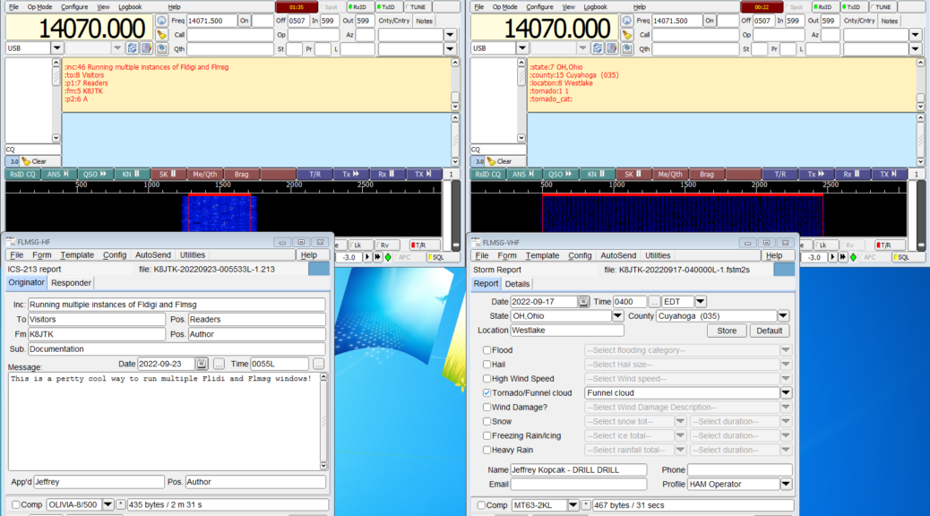
There are situations where it would be easier for an operator to run multiple instances (copies) of Fldigi and Flmsg at one time. These programs are often used for NBEMS handling over a repeater and the HF bands.
Why would anyone want to run multiple copies (or instances) of Fldigi programs? Some operators use HF and VHF/UHF differently including sound interfaces and rig controls. Instead of switching them around depending on which bands, have two instances configured differently for each radio. Other reasons could be using a single-all band-all mode radio but have different operating styles or personalities. Those could be Emcomm and contesting, or different macros and settings for each operating style. Monitoring multiple repeaters or HF frequencies during an Emcomm exercise. Or any combination of these examples. Creating separate instances will allow each to have separate settings, macros, and log books.
Fldigi and Flmsg with the default configurations are not setup to run multiple instances on a single computer. While the programs can be started multiple times, all instances share the same configuration directory. Setting different configuration directories allows one computer to run multiple instances all with different settings (rig control, audio devices, even Fldigi software versions). All instances can transmit and receive independently of each other on any combination of radios, bands, frequencies that can be connected to a single PC.
I’m demonstrating using the popular combination of NBEMS programs: Fldigi and Flmsg. It appears possible to run multiple instances of the other Fldigi suite of applications, such as flrig, fllog, flamp. Configuration changes for each program and communication between the programs would be needed. Additional programs are beyond the scope of this write up. Look at the program documentation for command line parameters, running multiple copies, I/O configuration page, and posts on groups.io support forums.
I will use the distinction of “HF” for an example instance connected to an HF radio, and “VHF” for an example instance connected to a VHF/UHF radio. There can be any number of instances created for however many radios or bands or operating styles are desired. The issue is manageability of settings, received files, and program updates.
This will work in Windows and Linux/Raspberry Pi. Substitute C:\Users\<Username> (Windows) with /home/<Username> (Linux) where <Username> is the logon for the user.
Program versions
Program versions used in this document.
Windows 7 – 64 bit
Fldigi 4.1.23
Flmsg 4.0.20
It appears Fldigi 4.0.18 and Flmsg 4.0.9 and greater support the command line options needed to run multiple instances.
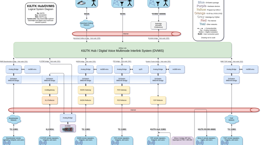
Presentation on Ham radio VoIP (Voice over IP) modes and the K8JTK Hub Digital VoIP Multimode Interlink System which integrates many Ham radio modes, both analog and digital.
Framework
The framework I chose to use for the presentation slides is called reveal.js. It is an HTML framework meaning it will run in any HTML 5 capable browser. Looks a little better than a PowerPoint presentation.
Navigation
Useful navigation keys in the presentation. In addition to navigating with the keys below, you can swipe (tables/smartphones) or use the navigation arrows on screen in the lower right.
Toggle full screen: press [F11].
Advance to the next slide: press [n] or [SPACEBAR].
Go back to the previous slide: press [p] or press and hold the [SHIFT] key while pressing the [SPACEBAR].
Display presentation overview: [ESC] then use the arrow keys or mouse to select a slide. [ESC] again will exit overview mode.
Links
Clickable links are colored in brown text.
Presentations
Three variations are available: presentation version is viewable in a browser. Printable version for printing or saving in a different format (Chrome, Chromium, and variants compatible only). Finally a PDF version.
They may take some time to load because I left original images untouched and some were a couple MB in file size.
Hurricane season wasn’t particularly fun in 2017. We had both extremes. Houston got hit with Hurricane Harvey which required little response from the ham community. Infrastructure stayed online. Disruption to communication systems and Internet was minimal. This left many hams wondering, ‘are we at the point where our infrastructure is stable enough to survive a category 4 hurricane?’ ‘Are hams still relevant since we were not needed for this type of event?’ We got the answer to those questions over the next month with two category 5 hurricanes. Irma impacted the state of Florida and Maria devastated the relatively poor U.S. possession of Puerto Rico. We went from wondering if ham radio was still relevant in emergency situations to rethinking training for extended deployment scenarios, all within a matter of weeks.
Ham radio news sources pointed out many communication techniques were utilized getting traffic in and out of affected areas. An ARRL press release indicated “Maxim Memorial Station W1AW at ARRL Headquarters is monitoring the HWN, 60-meter interoperability channel 2, and Winlink for any traffic.” Winlink gained prevalence in ham news media due to these disasters, gained popularity in emergency communications circles, and became an operating requirement for hams that assisted in Puerto Rico. Winlink is a very powerful and flexible system for exchanging all types of messages.
“Winlink (also known as Winlink 2000) is a worldwide radio messaging system that uses amateur-band radio frequencies to provide radio interconnection services that include email with attachments, position reporting, weather bulletins, emergency relief communications, and message relay” (Wikipedia). In other words, Winlink is a global email system via radio. The backbone uses the Internet for communication but users do not need an Internet connection. This makes the system popular in Emcomm when the Internet is not available. Winlink was first used recreationally by mariners, RV campers, and missionaries. The entire system is run by volunteers and a 501(c)(3) not-for-profit organization. Though similar in name, the “WIN System” is a popular IRLP repeater system based in California and entirely different.
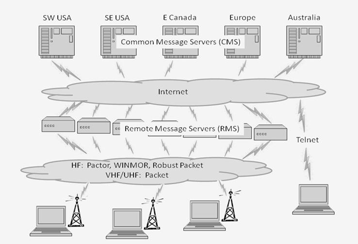
The Winlink system consists of multiple Common Message Servers (CMS) on multiple continents thought the world. The CMS servers form a “star” network configuration to coordinate traffic and provide services like email, webmail, telnet, bulletins, and reporting. Each CMS is a mirror image of the others for redundancy, failover, and outage situations. The Internet, by design, can work around outages. To date, there has been no global outage of the Internet – only regional. Having multiple servers, with redundant copies of the same data, means one or more could be affected by an outage and the system still functions. As of November 1, 2017, the CMS servers have been moved into the Amazon Web Services (AWS) cloud for greater redundancy.
Remote Message Servers (RMS) are scattered throughout the world and are the RF connection into the Winlink system. RMS gateways access the resources of the CMS servers via the Internet. These nodes are provided by hams familiar with the system and are setup on many ham bands (HF, VHF, UHF). On VHF/UHF, connectivity is limited to local clients. HF gateways serve a wider area but depend heavily on band conditions.
Finally, your computer runs the client software which interacts with services provided by the CMS, most often through an RMS gateway. The client software sends and receives messages. Size is limited to 120KB maximum, including attachments. Winlink uses a “store and forward” approach to messaging meaning clients are not constantly connected to an RMS or CMS gateway.
There are currently 6 client software applications available for Winlink. A feature comparison is available at: https://www.winlink.org/ClientSoftware. Winlink Express (formally RMS Express) is the preferred client because it’s developed by the system administrators and supports all features of the system. The software is well supported and frequently updated. The application looks and operates much like a stripped-down email client. Using a familiar email interface makes the application easy-to-use. Though free to download and use, Winlink Express is nagware. It will frequently prompt to purchase a key supporting development of the system. Registration of $24 is encouraged but not a requirement to use Winlink.
Winlink Express interacts with a wide selection of transceivers, provides different operating modes (PACTOR, Packet, Telnet, WINMOR Virtual TNC), and offers different connection methods (relay over mesh and D-STAR networks). It can be operated in any of four general methods:
Winlink: access messages on the CMS via an RF connection to an RMS gateway using the Internet.
Peer-to-Peer (P2P): messages exchanged directly with other users over RF, Internet, or mesh without the use of a RMS or CMS.
Radio-only: messages transferred between HF RMS gateways – without use of the Internet.
Telnet Post Office: connects to the CMS directly over the Internet.
A growing library of forms is available for ARES, RACES, SHARES, or MARS organizations including ICS, ARRL, and form types used in Ohio. The advantage of Winlink versus NBEMS is the ability to exchange messages over the public Internet. A form could be emailed directly to a government official instead of relayed via another ham. Winlink Express makes it easy to fill out or reply to forms by utilizing the local web browser. When composing a message, these forms are found under “Select Template.”
A “Query Catalog” accesses services provided by the CMS such as weather and marine forecasts, news, and propagation reports. Location coordinates can be reported through Winlink as well.
Winlink Express will work on a modern computer or Windows tablet running Windows Vista or later. The WINMOR Virtual TNC requires a 700 MHz or greater processor and 512 MB RAM or more due to the Digital Signal Processing (DSP) needed. An Apple or Linux version of Winlink Express is not available but it can be run using a virtual machine or dual-boot configuration. A Linux client is available but does not support all features.
This series primarily focuses on soundcard modes over HF and I will be discussing the WINMOR Virtual TNC. WINMOR is a low-cost interface utilizing the SignaLink USB for $120 as opposed to a PACTOR 3 dedicated hardware modem which can run $1,100 – $1,600. Low-cost hardware means tradeoffs. WINMOR is not anywhere near as fast or reliable as a PACTOR 3 modem, but it does a very good job.
To get started, first go to: ftp://autoupdate.winlink.org/User%20Programs/. Download two programs from the list of files: latest itshfbc program and Winlink_Express_install. ITS HF Propagation is prediction software to provide a rough estimate of the signal path quality between your QTH and remote RMS. Install both applications, order doesn’t matter. Click “next” through both installs, accepting defaults.
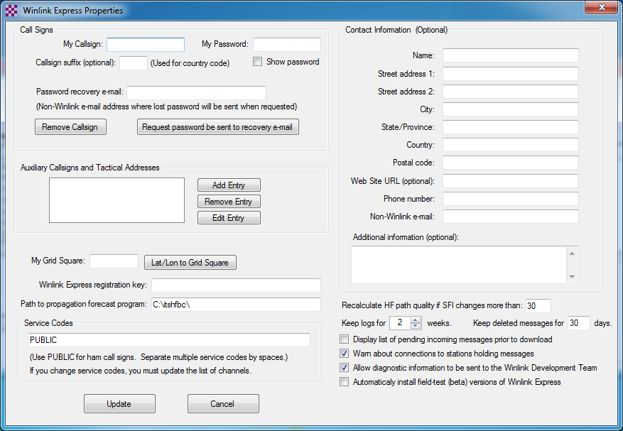
An Internet connection is required on the computer for initial setup. After starting Winlink Express, a “Winlink Express Properties” configuration will be seen. If not, click Settings, Winlink Express Setup. At a minimum the following fields must be completed: callsign, choose a password, enter a non-Winlink password recovery email, and grid square. Under Service Code, if you plan on using EMCOMM channels, make the code read: PUBLIC EMCOMM
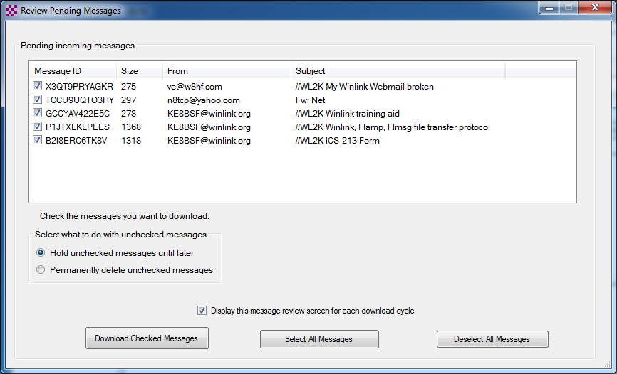
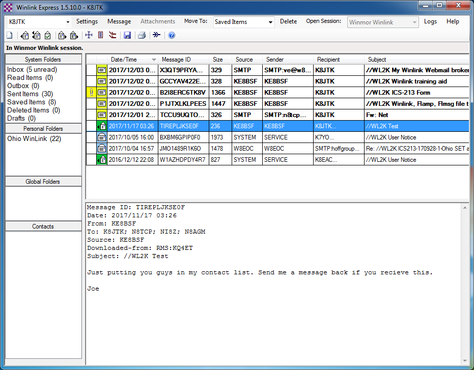
I recommend checking Display list of pending incoming messages prior to download. This will display incoming message details prior to download allowing the user to select or reject messages based on size or sender. Click Update. An account will be setup on the Winlink system. The Winlink email address won’t become active until a message is sent through the CMS gateway. Click Remind Me Later on any Winlink Express Registration screens.
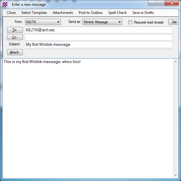
To create a message activating the Winlink email address, click the New message icon or click Message, New Message.
In the To field, enter your real email address. In the Subject field, enter something like “My first Winlink message.” In the message body, enter something like “This is my first Winlink message, whoo hoo!”
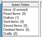
The message is ready to send, but wait! There is no “send” option. What gives?!? Since this system is store-and-forward, messages are Post to Outbox and appear in the “Outbox” System Folder. Messages in outbox can still be edited but will be sent when connected to a CMS.
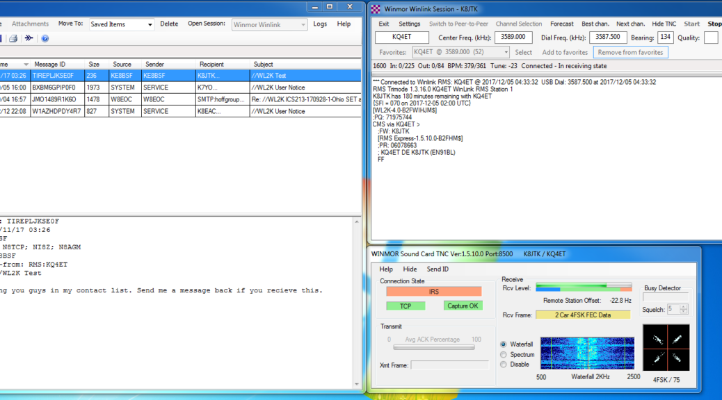
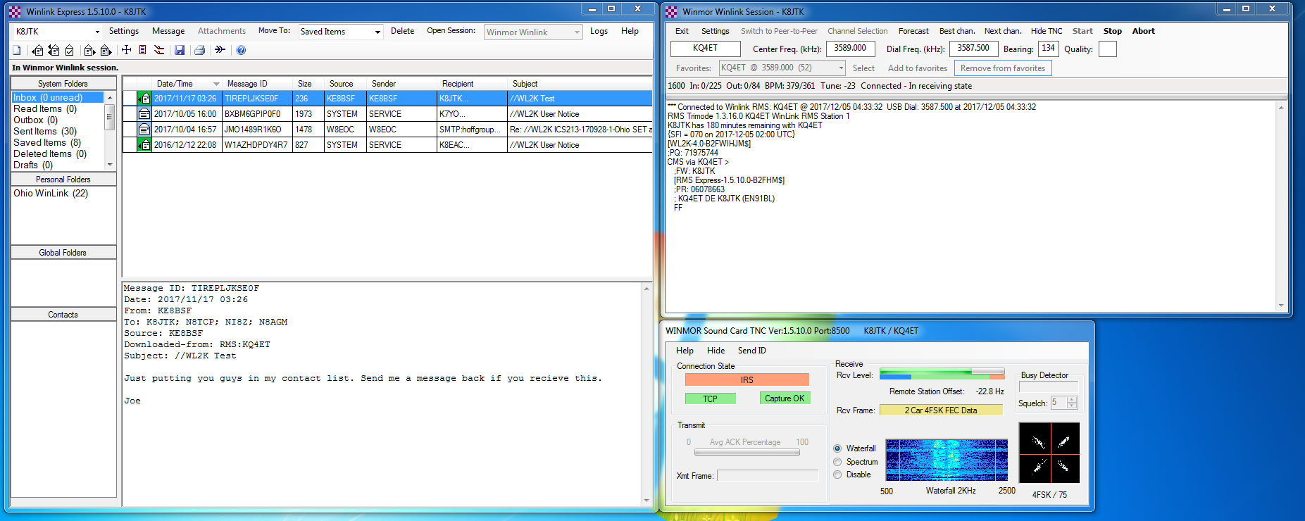
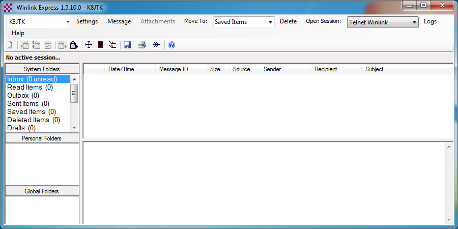
Next to “Open Session,” in the drop-down select Winmor Winlink. Click Open Session.
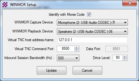
Two more boxes will appear: “WINMOR WL2K Session” and “WINMOR Setup.” The WINMOR WL2K Session box is where an RMS gateway is selected and it displays the connection status.
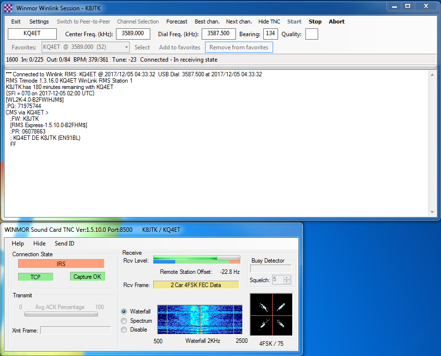
You will be prompted to select the Capture and Playback soundcard devices in the WINMOR Setup box. For the SignaLink, select USB Audio CODEC. Leave all other settings at their defaults. Click Update. A third “WINMOR Sound Card TNC” box will appear. This window shows a waterfall along with transmit and receive state of the virtual TNC. Ignore this box for now.
On the SignaLink, begin with the TX and RX volume knobs set to the 12 o’clock position. Set delay (DLY) to the 2nd tick-mark (8 o’clock position).
If you have a way to control your radio through CI-V commands or equivalent, click Settings, Radio Setup, and configure the settings for the radio. Radio control makes it much easier when selecting different RMS gateway stations. Selecting a different station will automatically change the radio’s frequency and mode. With a VOX device like the SignaLink, for “PTT Port” select External. Click Update.
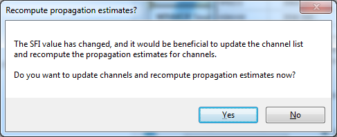
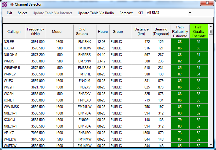
Back in the WINMOR Winlink Session box, click Channel Selection. An “HF Channel Selector” window will open. A message will ask to ‘update the channel list and recompute the propagation estimates now?’ Click Yes. If not asked, click Update Table Via Internet. This table will update with the current list of Winlink RMS gateway channels on HF. The list can be updated over radio in the future if desired.
Once updated, the presence of color in the “Path Reliability Estimate” and “Path Quality Estimate” columns mean the ITS HF Propagation predictor program is installed and working. Calculations are based on your grid square and solar flux index. Update the current grid square in Winlink Express setup and this table often when traveling. “Mode” is the bandwidth of the RMS node. A higher number means faster transfers are possible. “Hours” means the hours each day the node is online. “00-23” is all day, “02-13” is 02:00 – 13:00. The rest is self-explanatory.
To select a particular RMS gateway, double-click that row in the table. Gateways in green are good choices but ones at the top of the list may not always provide the best connection. Reliable gateways are found by trial and error and can be added to the “Favorites” list. If Rig Control is enabled, the radio should tune to the dial frequency of the RMS gateway and enter USB mode. If not, tune the radio’s display frequency to the “Dial Freq” (VERY important!) shown in WINMOR. Warm up the Tuner if it needs it. Remember to use no more than 30% power. Click Start.
If WINMOR thinks the channel is busy, it will prompt to verify you still want to connect because your transmissions maybe interfering with another station. Your radio will start pinging the remote RMS gateway station. In the WINMOR Sound Card TNC, above the receive indicator will be the “Measured T>R Latency” value. This measures the transmit/receive turnaround time. This should be less than 250ms and adjustable in part by the SignaLink DLY knob. Higher values will cause problems receiving from the RMS gateway. While receiving transmissions from the gateway, adjust the RX knob to a level that falls within the green portion of “Rcv Level.”
With any luck, your client will connect and your first Winlink message will be sent! There will be A LOT of back-and-forth (TX/RX switching) between your radio and remote RMS gateway. These are handshaking and acknowledgments or sending/receiving messages. When all messages are exchanged, the client will automatically disconnect from the RMS gateway. Clicking “Stop” will gracefully disconnect and ID at any time during a session. “Abort” should only be used when something is very wrong because communication is terminated immediately (without ID). Attempts will be made by the RMS to reestablish communication with the client before eventually timing-out.
Once the test message is received in your actual email, your new callsign@winlink.org email address is now active! Send a reply to the test message through your real email. To call a different RMS gateway, click Channel Selection and select a different station. Wait 5 minutes or so for the reply email to reach the Winlink CMS. Click Start in the WINMOR Winlink session box. You will see your reply downloaded to the inbox! When replying to lengthy messages, I will keep a few sentences (paragraph at most) of the original message. This keeps the transmission time down. The original sender can look at the full message in their client sent folder.
Before going crazy telling people to send messages, there is one crucial piece to this system. Winlink uses a “whitelist” (approved senders list) approach for external email addresses. This keeps abuse and spam to a minimum. As a Winlink user, you are free to send messages using your Winlink address to other Winlink users. Other Winlink users can do the same, freely contacting you.
External email addresses are handled very different. An external email is any mail system other than Winlink (Gmail, Outlook, DACOR, Buckeye Cable, BGSU, etc.). If you first send a Winlink message to someone@someprovider.com, that email address is automatically added to your Winlink whitelist. That means email from someone@someprovider.com will be delivered to your Winlink inbox.
For an external email address to send you a message unsolicited to Winlink, there are two options: add that email to your whitelist ahead of time or the sender must put “//WL2K” in the subject line. Example: “//WL2K Holiday Meeting.” Anything with //WL2K in the subject is considered a deliverable message and will not be flagged as unauthorized. By default, all outgoing messages have this inserted automatically by Winlink Express. When some individual replies to your message, which would have //WL2K in the subject, it will be accepted. Any non-whitelisted (blacklisted) addresses or messages without //WL2K in the subject, the sender will receive a bounced error message saying “Sender not authorized for any recipient.”
Whitelists can be managed by logging on to the Winlink My Account page and click My Whitelist. That page will provide details how to update the whitelist using client commands, if desired.
Another important detail to remember, there is no expectation of privacy with the Winlink system. RMS gateway owners and Winlink administrators can read messages exchanged through the system. They are looking for Part 97 violations and inappropriate usage of the system. Violators will be blocked. I’m sure they would find details of your camping trip fascinating, but they really don’t care.
Email messages through this system are considered 3rd party traffic under Part 97. The email message resides on the CMS until you (a ham) make a connection to another ham’s station (RMS) to retrieve your messages. This is similar in nature to passing messages over the National Traffic System (NTS).
The list of services available through the Winlink system is extensive. Winlink is quite flexible allowing many different ways to access the system over RF, APRS, or Internet. Feel free to send a message to my Winlink email address, K8JTK—at—winlink.org. Replace “—at—” with the appropriate email symbol. Don’t forget to include //WL2K in the subject!
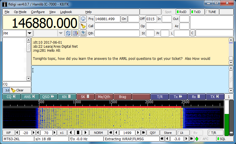
Have you ever been involved with an EmComm/ARES drill and heard digital tones as forms were being passed over a repeater? You may have wondered what application are they using, what mode, or how do they know what form is being sent? Chances are they utilized an established standard called NBEMS. The Narrow-Band Emergency Messaging System was created to pass text based messages and forms used by hams and other served agencies over Amateur Radio. Technicians, listen up! NBEMS includes standard modes for HF SSB and is very popular on VHF/UHF FM.
NBEMS was established in collaboration between David Freese, Jr. – W1HKJ who created and maintains the Fldigi suite of applications and Skip Teller – KH6TY who created DigiPan, a popular PSK application. The philosophy specifies utilizing radios, software, and hardware readily available and widely used in ham radio. Older equipment and older computers can be used meaning it would be relatively inexpensive. There would be no steep learning curve but flexible in an emergency situation. Finally, must be independent of infrastructure. No need for Internet, nodes, or existing communications systems. Power the computer, radio, interface, and you’re off-and-running.
Interfaces between the computer and radio used for other digital modes work best. In accordance with the flexible and inexpensive philosophy, another option is available: no interface at all. That’s right, you don’t need any interface between a computer and radio in order to communicate. To receive data, the radio speaker is held to the computer microphone. To transmit, the radio microphone is held to the computer speaker. This method is called an “acoustic interface.” It’s a game saver in a pinch, doesn’t require any additional hardware, and allows anyone with a radio and PC to participate. The digital protocols used are robust enough to deal with ambient noise, casual conversations, too much audio, too little audio, and still be able to decode 100%.
Though operating without an interface sounds like the best of all possible options, there are serious drawbacks. Transmitting (PTT) is done manually. Longer messages mean the operator has to hold PTT in longer. If their finger accidentally slips off the button, the message needs to be retransmitted. The operator needs to be more attentive to the station where it’s possible they may become distracted and miss messages. In a conference or war room, transmitting and receiving messages acoustically adds a layer of disruption to the setting. A connected interface would handle the keying, always provide audio to the computer for decoding messages – even while away from the station, and would not generate any additional noise effectively allowing the station to be completely quiet. As a whole, digital modes are not designed to work through an acoustic interface because most are sensitive to noise. Noise introduces errors making all or part of the transmission unrecoverable. An acoustic interface is a good way to practice or start, though the efficiency of a connected interface will soon be realized.
NBEMS utilizes two different modes: VHF/UHF uses MT63-2000L, HF uses Olivia 8/500. Both were developed by Pawel – SP9VRC.
It is surmised that 25% of the characters in an MT63 transmission can be lost and the receiving station will still have a perfect copy. This is achieved by encoding characters over the time and frequency domains for robustness. In addition, the “L” versions have additional (long) interleaves providing even more error correction. MT63 is very forgiving of audio levels and tuning errors making it a great choice for EmComm. The suffix indicates bandwidth used, 2000/2K means 2 KHz. Transfer rate is about 1 KB/minute.
Olivia 8/500 is used on HF because signals can be decoded below the noise. Low power and QRP stations can communicate nearly as effectively as a higher power station. A channelized approach is used because signals below the noise can be decoded but not heard or seen on the waterfall. The 8/500 indicates 8 tones utilizing 500 Hz of bandwidth. Fldigi suite reverses these in places, 500-8. Transfer rate is about 170 bytes/minute.
A common question brings up the issue of popularity. PSK31 and JT65 are two popular modes on HF. Both are not used in NBEMS because there is no error correction for weak or fading signals in PSK. A faster, multicarrier PSK-R (for Robust) mode is occasionally used in NBEMS but I have not seen many groups use it as an established standard. JT65 is limited to 48 second timed transmissions of 13 characters which is not efficient for data transfer.
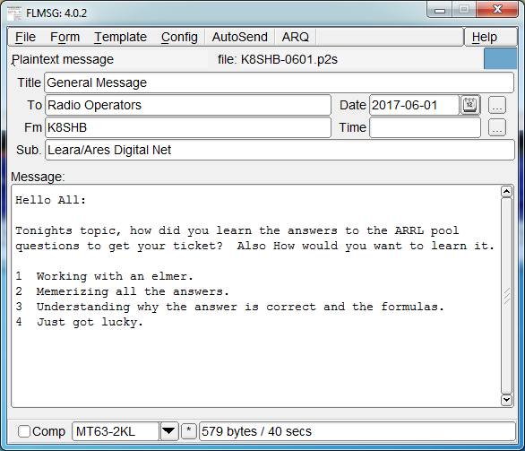
Two applications are synonymous with NBEMS: Fldigi and Flmsg. In the last article, I talked about Fldigi being one of the more popular multimode applications. Flmsg is another application in the Fldigi suite that manages forms. It can be used to send standardized agency forms like ICS, Red Cross, or MARS. Forms developed by local agencies can be coded as a “custom form.” Plain text (.txt) and comma-separated (.csv) files can be transferred. Sticking to the inexpensive and flexible philosophy, the entire Fldigi suite of applications are free, open source, and cross platform available on Windows, Mac, and Linux including Raspberry Pi. Custom forms are a popular use of Flmsg however, these forms need to be disseminated or available online ahead of time.
Other applications like DM780 and MultiPSK can send and receive both MT63 and Olivia. These don’t have provisions for managing forms or validating transmissions. Fldigi and Flmsg are integrated seamlessly to pass data between the form manager and modem application.
A very important behind the scenes, but not often discussed feature in NBEMS is the checksum. In computing, a checksum is used to detect errors in transmission or in storage. Flmsg automatically generates and includes a checksum as part of the message with each transmission. Receiving stations calculate a checksum value based on the data received and compare it against the value included in the message. This is an ease-of-use feature letting receiving stations know if they received a prefect copy of the message. If the checksum matches, Flmsg will open displaying the form or message. If the checksum fails, this means an error was introduced in transmission. As a result, the message will not open or a “Checksum failed” prompt will be seen.
Example message:
... start

[WRAP:beg][WRAP:lf][WRAP:fn K8JTK_Digital_Communications_in_Amateur_Radio-_NBEMS.p2s]<flmsg>4.0.2

:hdr_fm:21

K8JTK 20171807024326

:hdr_ed:21

K8JTK 20171807024320

<plaintext>

:tt:46 Digital Communications in Amateur Radio: NBEMS

:to:6 Reader

:fm:5 K8JTK

:dt:10 2017-07-17

:tm:5 2233L

:sb:12 Demo message

:mg:44 This is an example message in an NBEMS form.

[WRAP:chksum 2CBF][WRAP:end]

... end
A checksum value is included in the “WRAP” tags and is 2CBF for this message. Upon receipt of this message, Fldigi automatically calculates a checksum for verification. If it arrives at the value of 2CBF, the message was received perfectly.
There are limitations of NBEMS that users and served agencies need to be aware. To meet FCC requirements, all data must be transmitted within 3 minutes on a repeater with a standard time-out-timer or 10 minutes on simplex. This means a maximum file size for MT63-2KL on a repeater is 3,000 bytes and 1,700 bytes for Olivia 8/500 on simplex. These properties severely limit the content that can be transferred to text. Word documents need to be converted to TXT and Excel spreadsheets to CSV files in order to save bandwidth. There are not many useful images, Word documents, Excel spreadsheets, and executable programs under 3K. This makes high-resolution images and large data transfers impractical using NBEMS. Remember, it is a Narrow-Band Emergency Messaging System.
Reminder: review the first two articles in the series for information that will be omitted here including some modes operate your transceiver at 100% duty cycle, use upper sideband (USB), and don’t drive the transmitter with too much audio as the signal will be wider than intended. Operating data over FM is the same as operating voice and does not change the duty cycle of the radio. However, operating FM at high power for prolonged periods of time is considered extreme for most radios and will likely shorten the life of the transceiver. In addition, review the fourth article on “Conversational Modes” as Fldigi was covered.
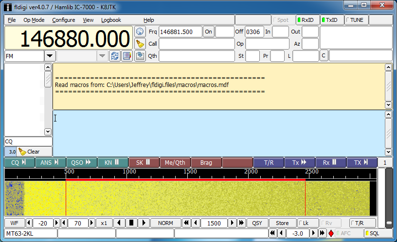
With Fldigi setup and working, download and install Flmsg from http://www.w1hkj.com/. To prepare Fldigi for VHF/UHF NBEMS, click Op Mode, select MT63, and click MT63-2000L. MT63-2000L is also abbreviated as MT63-2KL in other places within the Fldigi suite. These are the same, 2K = 2000. With MT63-2KL selected as the active mode, now center the receive window on the waterfall at 1500. 1500 Hz is the standardized center frequency. For HF NBEMS, replace MT63-2000L references with Olivia 8-500.
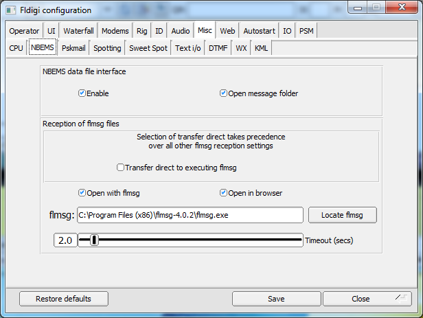
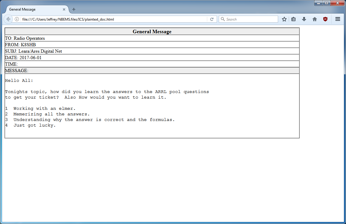
Fldigi passes data to Flmsg for decoding and displaying. Fldigi needs to know where to find the Flmsg installation. In Fldigi, click Configure, select Miscellaneous, then click Misc to enter the Miscellaneous program options. Finally, click the NBEMS tab. In newer versions of Fldigi (later than 3.23.0), uncheck the Transfer direct to executing flmsg. Open with flmsg and Open in browser should be checked if they are not already. Now click Locate flmsg. Depending on the version of Windows, the default installation location for Flmsg will be C:\Program Files (x86)\flmsg-x.x.x or C:\Program Files\flmsg-x.x.x. In that directory, select the flmsg application, click Open. Click Save, then Close.
“x86” is a Windows designation to differentiate 32 bit from 64 bit applications on a Windows 64 bit installation. “x.x.x” is the version of Flmsg. Each time a new version of Fldigi, Flmsg, or any other Fldigi application is installed, it is kept in a separate directory with the version appended. Alot of versions can accumulate on a system if frequently updated. Anytime uninstalling or using a new version of Flmsg, the steps above for “locating flmsg” need to be repeated.
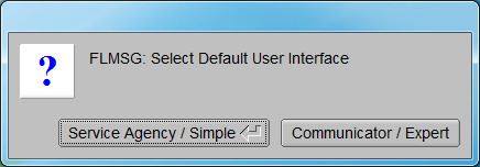
Start Flmsg. A dialog prompting for the selection of a “Default User Interface” will be seen on a new installation, click Communicator/Expert. Station information will be requested. These are used as inputs for some forms. Call sign should be filled in as a minimum. Click the red “X” when done filling in station information. At the bottom of the main Flmsg window is the mode selector. Click the down arrow and select MT63-2KL.
Configuration is done!
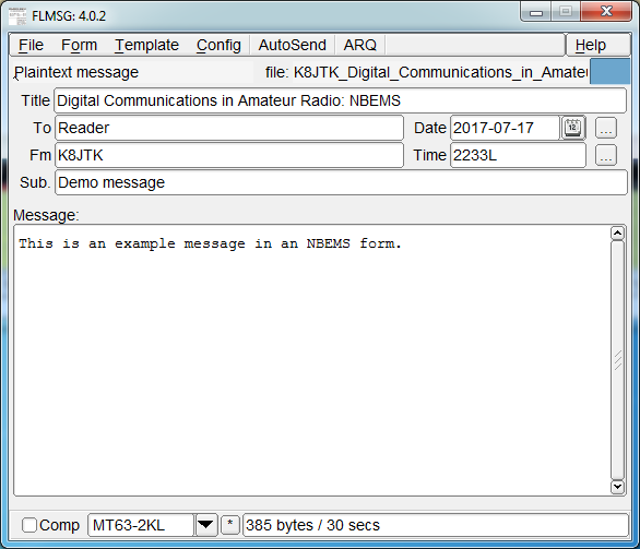
To use Flmsg, a blank Radiogram will open initially. To select a different form, click Form. Different types of available forms are categorized: ICS, MARS, Radiogram, Red Cross, weather, and custom forms loaded will be available from this menu. Choose any form for practice. Standard practice is to note somewhere in the form that this is a “test,” “practice,” or “drill.” As with voice, someone may mistake the transmission for a real message.
Once the form is filled out, set your radio to the appropriate frequency and open Fldigi if it is not already. Set it to MT63-2KL centered at 1500. Verify the mode selected in Flmsg is MT63-2KL. Click AutoSend. The file must be saved before it will transmit. Once the file is saved, transmission will begin automatically. Get into this habit of checking transmit frequency, Fldigi configuration and Flmsg configuration before clicking AutoSend. Otherwise you will inadvertently transmit on a different frequency or in a different mode. It happens to everyone eventually.
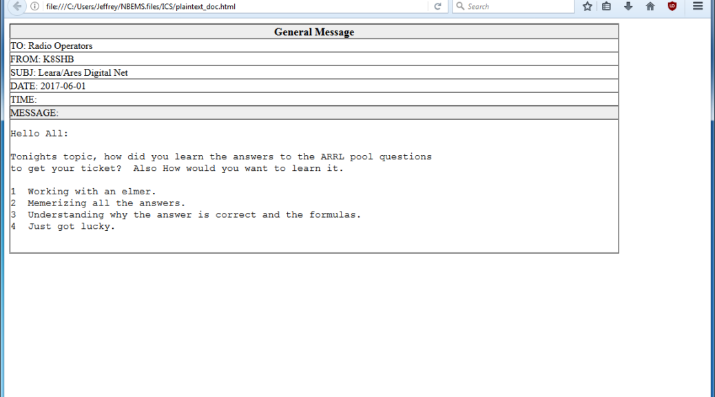
Receiving stations only need to open Fldigi. They will first see the message appear in the Fldigi receive pane. The form type is transmitted as part of the message. In the example message, <plaintext>. The lines begin with the form field name and check of the number of characters in that field. “:fm:5 K8JTK” is the “from” field with a check of 5 characters, “K8JTK“. When completed, an Flmsg window will open. The form will also be rendered in the default web browser. Receiving stations don’t have to do a thing except wait for the transmission to complete. If the next message received is a Radiogram, Flmsg will automatically open a window and browser page displaying the Radiogram format.
That’s it for using NBEMS! I have a more detailed setup and walk through of installing and configuring Fldigi and Flmsg. My instructions include another Fldigi suite application called Flwrap. Flwrap allows files of any type to be transferred. It sounded, at one point, like it was going to be part of the standard set of NBEMS applications but never made it due to the file size constraints. Additionally, Flmsg performs similar functionality to Flwrap in its ability to send TXT & CSV files. The Flwrap parts can be skipped unless they are found useful.
Typically, you’ll need to setup a sked or hold a net to pass messages around. Operators don’t sit around watering holes sending Flmsg messages, though I have seen it! Use news on QRZ.com or ARRL Ohio Section updates as text to fill out the forms as practice. Participating in a couple different nets, there seems to be less problems when everyone is using the same versions of the applications.
An Android smart phone app is available at the same site as Fldigi called AndFlmsg. There is a INSTALL.txt file with install instructions. The app is not available through any of the Android app stores and must be installed by temporarily enabling the option to allow applications from “Unknown sources.” A user guide is available in the same directory as the download. This will be helpful as the interface is not entirely intuitive.
The Ohio Digital Emergency Net (OHDEN) is a weekly HF practice net that uses the Olivia standard. Checkins and coordination is accomplished using the text input box in Fldigi. There is no voice coordination. Formal messages don’t happen every week but are passed using Flmsg. OHDEN meets Tuesdays at 7:45 PM eastern on 3.585 USB using Olivia 8-500 centered on 1000 Hz.
You picked up a new DMR radio! Congratulations! You maybe thinking, what have I gotten myself into? Good question. DMR is the first commercial mode adopted for ham radio use. Terminology and radio setup are familiar to those who program commercial gear. If you’re coming across this programming example and have not read the first part on terminology, please do so as this will build upon it. Passing around a code plug makes DMR seem plug-and-play and it’s a great way to get started. Doing so tends to leave most of us unable to change the configuration of our own radios. My goal is to demonstrate how to program a DMR ham radio code plug from scratch. This will lead to understanding how code plugs work and how to modify them. I will demonstrate programming a code plug for an example repeater, hotspot, and simplex operation.
In addition to this example, I recommend looking at available code plugs online to get an idea of different ways to improve yours. This is how I learned to program code plugs. There is no central database or repository. Code plugs are scattered around the Internet and shared online. This makes sense because local users would know where to get a code plug. Ask others in the area with similar DMR radios where to find code plugs. The ARRL Ohio site has ones for Ohio’s DMR repeaters: http://arrl-ohio.org/digital/digital.html. Where this works for local hams, a scavenger hunt is required to find working code plugs for an area they’re visiting.
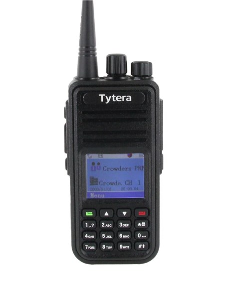
Screen shots and settings referenced in this tutorial are from the TYT MD-380 CPS and radio. Similar settings can be found in other programmers and radios. Functions of not-so-obvious radio settings are described in the appropriate sections.
Software (TYT & Connect Systems)
Updating settings and memories in all DMR radios requires a computer, programming cable, and CPS. Check radio packaging because some include the cable and software, others consider it an additional accessory. Most stock CPSes can’t rearrange entries or import from other sources. If you entered a new contact and wanted to rearrange the order, you can’t. If you want to import thousands of users, you can’t. Third-party code plug editors provide this additional functionality. All are freeware.
TYT MD-380 / 390 Code Plug Editor: http://www.miklor.com/DMR/DMR-380-CPEditor.php
Editor for importing/exporting settings, importing from the DMR-MARC user database, and rearranging entries. The TYT CPS is still needed to write the code plug to the radio. This is my preferred MD-380 editor.
N0GSG’s DMR Contact Manager: http://n0gsg.com/contact-manager/
Works for most models of Connect Systems, Tytera, Retevis, and AnyTone radios. Editor can import/export settings and import contacts from the DMR-MARC user database, comma separated file (CSV), or existing code plug. Sorting is accomplished by clicking the header columns. Radio CPS is still needed to write the code plug to the radio.
The last three are free to use but please consider a donation to the developer if you find their work useful.
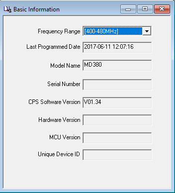
Radio ID, general settings, and FPP
After installing the CPS, in “Basic Information,” first check the “Frequency Range” is correct for the radio.
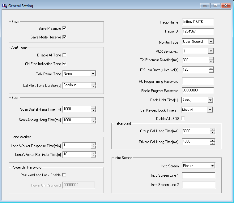
First thing to program is your “Radio ID.” You registered for one, right? It is found in the CPS under “General Settings.” Enter your assigned CCS7 ID. When passing around a code plug or loading someone else’s, update the CCS7 ID otherwise you will appear as someone else.
The “Radio Name” can be whatever name you want to give the radio.
I like to have a notification when the transmission is complete and the channel is free. This is known as the ‘CH Free Indication Tone.’ NOTE: this tone did not work with the DV4Mini for some reason.
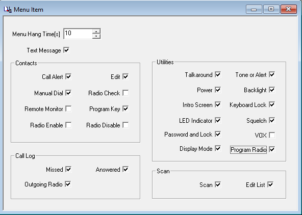
Enable FPP so the programming can be modified from the radio’s keypad. Remember to read the radio or update changes made through FPP into the CPS. Changes will be overwritten when the code plug is downloaded again to the radio. In the CPS, FPP can be enabled in “Menu Item,” under “Utilities,” check “Program Radio.”
To enter FPP mode on the radio, go to the menu, select “Settings,” and “Program Radio.” The “Radio Program Password” in “General Settings” of the CPS is used when entering FPP on the radio. This is a commercial carryover to keep users from screwing with the radio. Enter the program password, if needed, and voila.
Hang-time, delays, and other adjustments can be made and experimented with at your leisure.
Programming example
In order to successfully program a code plug for a repeater, Color Code, talk group, and time slot configuration must be known. This information can be obtained from RepeaterBook, RFinder, owner/club website, asking another user or the repeater owner. Also ask if the repeater has access to reflectors, if desired. Brandmeister and DMR-MARC repeaters have reflector access.
A configuration example of a factitious repeater is outlined below. I’ve picked common U.S. talk groups for each time slot and will use the “Area 8” reflector as examples. When you become more comfortable, substitute the local repeater’s information.
Private calls to individuals are never a mandatory part of repeater configuration. They are possible and will be shown as an example. I include private call channels for frequent contacts as part of my hotspot code plug.
The “type” column in the table below is for informational/clarification purposes only and would not necessarily be provided by the owner (see the previous terminology write-up).
Labeling and organization of the code plug is user preference. RX Group lists and channels will need an abbreviation or prefix noting to which system it applies. When programming even 10 repeaters, some distinction must be made for clarity. Prefixes help programming because similar items are grouped together in the CPS. Rationale behind this will become clearer as you add repeaters to a code plug. Some might like to have the city spelled out (Cleveland, Dayton, Columbus, Cincinnati, Toledo) while having the talk groups abbreviated (WW, NA, Lcl 9, TAC-311, Statewide). Others like to have the city abbreviated (Cle, Day, Col, Cin, Tol) while the talk group is spelled out (World-Wide, North America, Local 9, TAC-311, Ohio). No two items may have the same exact name in any one area: Contacts, RX Groups, Channels, Zones, or Scan Lists. “SC” will be the prefix used for this example to indicate “Some City.”
Call: K8XXX
City: Some City, OH
Output: 444.300
Input: 449.300
Color Code: 1
Label
Type
ID
Time Slot
World-Wide
Talk group
91
1
North America
Talk group
93
1
USA – Nationwide
Talk group
3100
1
Local 9 (or Reflector)
Talk group
9
2
TAC-310
Talk group
310
2
TAC-311
Talk group
311
2
TAC-312
Talk group
312
2
Midwest (regional)
Talk group
3169
2
Ohio (statewide)
Talk group
3139
2
USA – Area 8
Talk group
4648
2
Individual contact
Scott N8SY
User
3139437
N/A
Contacts
Digital contacts are required to be setup first. These drives the ability to build RX Lists and channels. Every talk group, reflector, or user gets a contact. Relevant information in the table above: Label, Type, and ID.
It’s best to follow the labeling/naming provided by the c-Bridge. Some radios don’t have a lot of display real estate and names must be shortened to something like “WW” for talk group 91, “NA” for 93.
There are four fields per “Digital Contact” record in the CPS:
Contact Name
Call Type
Call ID
Call Receive Tone
“Contact Name” is simply the name you give each contact and is the label seen on the radio while receiving a call from that ID. “Call Type” is group/private/all-call setting. “Group” is for talk groups and “Private” is used for radio-to-radio calls or commands. “Call ID” is the numeric talk group, reflector, radio ID, or command number. “Receive Tone” is a per-call setting where a tone is emitted from the radio prior to unmuting the audio. This can be used as notification prior to receiving a call from a contact of interest.
There cannot be two contacts with the same “Call ID” or the same “Contact Name.” When programming different repeaters, potentially on different networks, all talk groups for all c-Bridges are entered as contacts. If two networks label talk group 3333 differently, a generic display name will have to be chosen, such as “3333” or “Group 3333.” On the other hand, “Example talk group” is talk group ID 3333 on one network and ID 3344 on another, then two differently named contacts have to be created for the same talk group (ie: “ExTG 3333” with ID 3333, “ExTG 3344” with ID 3344).
If the repeater owner says they follow K4USD’s talk group layout for example, they have nearly 70 available talk groups on their c-Bridge. Though it seems like a lot of work at the time, I recommend creating contacts for all 70 available talk groups. Having all talk groups programmed will result in less effort changing the code plug later. Brandmeister on the other hand, good luck. You really have to decide which talk groups are of interest because all talk groups are available to all repeaters and hotspots. To keeps things simple, stick with the repeater owner’s suggested Brandmeister groups.
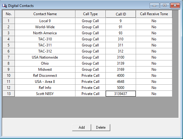
For this programming example, contacts are pre-sorted by ID number. In the CPS software, create Digital Contacts with the listed settings:
Contact #1
Contact name: Local 9
Call type: Group call
Call ID: 9
Receive tone: No
Contact #2
Contact name: World-Wide
Call type: Group call
Call ID: 91
Receive tone: No
Contact #3
Contact name: North America
Call type: Group call
Call ID: 93
Receive tone: No
Contact #4
Contact name: TAC-310
Call type: Group call
Call ID: 310
Receive tone: No
Contact #5
Contact name: TAC-311
Call type: Group call
Call ID: 311
Receive tone: No
Contact #6
Contact name: TAC-312
Call type: Group call
Call ID: 312
Receive tone: No
Contact #7
Contact name: USA Nationwide
Call type: Group call
Call ID: 3100
Receive tone: No
Contact #8
Contact name: Ohio
Call type: Group call
Call ID: 3139
Receive tone: No
Contact #9
Contact name: Midwest
Call type: Group call
Call ID: 3169
Receive tone: No
Contact #10
Contact name: Ref Disconnect
Call type: Private call
Call ID: 4000
Receive tone: No
Contact #11
Contact name: USA – Area 8
Call type: Private call
Call ID: 4648
Receive tone: No
Contact #12
Contact name: Ref Info
Call type: Private call
Call ID: 5000
Receive tone: No
Contact #13
Contact name: Scott N8SY
Call type: Private call
Call ID: 3139437
Receive tone: No
Notice contacts #10 and #12 are not listed in the example table. These are standard reflector commands. A private call to ID 4000 is required to disconnect the repeater, 5000 checks link status. Talk group 9 is also required for reflector use. See the Reflector section for usage.
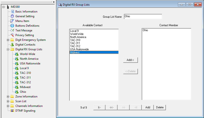
(Digital) RX Group lists
Once Contacts are entered, RX Group lists can be created. Relevant information from the example table: Label and Time Slot. RX Group lists are limited to a maximum of 32 talk groups per list. The intent was to monitor all talk group activity on a time slot. Only contacts set to “Group Call” can be added.
There are generally two ways of creating RX Groups. The first uses a one-to-one relationship where each talk group has its own RX Group List. The second includes all available talk groups on a repeater’s time slot into a single list. The latter creates lists unique to a repeater that cannot be reused on another repeater, unless the configuration is exactly the same. If the repeater has less than 32 talk groups on a time slot, put them all in one RX Group list. If there are more than 32, then create one RX list per talk group.
To keep repeater specific group lists unique, name the list: repeater location followed by “TS1/2” for the time slot designation. Example: “Some City TS1,” “Some City TS2.”
RX Group lists and the RX list selected for a channel are the first places to look when there is a suspected radio programming issue or nothing is being heard.
A repeater specific example is provided later. For this programming example, the one-to-one relationship is demonstrated. RX Groups are created in the same order as the repeater listing. In the CPS software, create RX Group lists and include the listed contact(s):
Digital RX Group List #1
Group List Name: World-Wide
Available Contact, select and add: World-Wide
Digital RX Group List #2
Group List Name: North America
Available Contact, select and add: North America
Digital RX Group List #3
Group List Name: USA Nationwide
Available Contact, select and add: USA Nationwide
Digital RX Group List #4
Group List Name: Local 9
Available Contact, select and add: Local 9
Digital RX Group List #5
Group List Name: TAC-310
Available Contact, select and add: TAC-310
Digital RX Group List #6
Group List Name: TAC-311
Available Contact, select and add: TAC-311
Digital RX Group List #7
Group List Name: TAC-312
Available Contact, select and add: TAC-312
Digital RX Group List #8
Group List Name: Midwest
Available Contact, select and add: Midwest
Digital RX Group List #9
Group List Name: Ohio
Available Contact, select and add: Ohio
Notice contacts #10-13 cannot be included because they are set to private call.
Repeater specific, all talk groups per time slot example:
Digital RX Group List #1
Group List Name: Some City TS1
Available Contact, select and add (position 1): World-Wide
Available Contact, select and add (position 2): North America
Available Contact, select and add (position 3): USA Nationwide
Digital RX Group List #2
Group List Name: Some City TS2
Available Contact, select and add (position 1): Local 9
Available Contact, select and add (position 2): TAC-310
Available Contact, select and add (position 3): TAC-311
Available Contact, select and add (position 4): TAC-312
Available Contact, select and add (position 5): Midwest
Available Contact, select and add (position 6): Ohio
Channels
This is where it all comes together. To create channels, Contacts and RX Group lists need to have been established.
Analog channels are straight forward if you’ve programmed any other analog ham radio. They will not be covered here.
Channels for the same repeater are easier to copy and paste. This depends on the software but usually involves setting up a channel, copying that channel, creating a blank channel, and pasting over the blank channel.
Some settings definitions:
Admit Criteria: determines when the radio is allowed to transmit.
Always: allows the radio to transmit any time PTT is pressed. This is the most disruptive option and may interrupt another QSO in progress.
Channel Free: the radio will only transmit when there is no transmission in progress on the time slot.
Color Code (Free): the radio will only transmit when the time slot is free on the repeater matching the color code. This mode pings the repeater at the beginning of each transmission to find a matching color code. This pinging is also an indicator if you’re making the repeater or if it is in use.
“Color Code” is recommended for a repeater, “Channel Free” for hotspot & simplex use.
In Call Criteria: action taken while receiving a call and the PTT button is pressed. This can be thought of as the ‘interrupt a call’ setting.
Follow Admit Criteria: follow the setting defined in “Admit Criteria.”
Always: always transmit, even while receiving a call.
“Follow Admit Criteria” is recommended for a repeater, “Always” for hotspot & simplex use.
Auto Scan: when the channel is selected, the radio begins scanning channels defined in the selected “Scan List.” For this option to function: create channels, add the channels to a Scan List, then create another new channel with the newly created Scan List selected and “Auto Scan” checked.
Lone Worker: the user receives an alert from the radio after a specified amount of time and must acknowledge by pressing any button on the radio. If the user does not respond to the alert, it is assumed the user is injured or incapacitated. The radio switches to an emergency mode so the user can be located and assisted. I have not seen this used in ham radio.
Allow Talkaround: this allows the radio to operate simplex mode when a repeater is not available or out-of-range. TX and RX frequencies must be different for this option to function. Talkaround is enabled/disabled manually via the radio’s “Utilities” menu, select “Radio Settings,” select “Talkaround,” then select “Turn On/Off.”
Emergency System: settings for an emergency alarm. I have not seen this used in ham radio.
Privacy: DMR includes the ability to “scramble” transmissions. This is a form of encryption and not allowed in the US.
A clear definition of “RX/TX Ref Frequency” has not been found and understood the default setting is sufficient.
Provided by Rich – G3ZIY:
These two drop-down selections are provided to change the radio’s basic oscillator frequency in the receive or transmit side. Because the radio covers such a wide frequency range, on some specific receive or transmit frequencies there can be a birdie generated internally which interferes with reception or transmission. If this occurs, by simply trying a different setting from the current setting, it should be possible to get clear reception and a clean transmission.
Leave “TX/RX Ref Frequency” at the default unless you experience problems transmitting or receiving and tack the problem down to the radio itself.
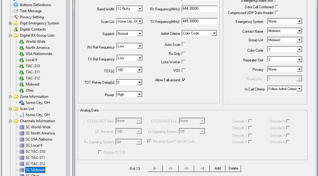
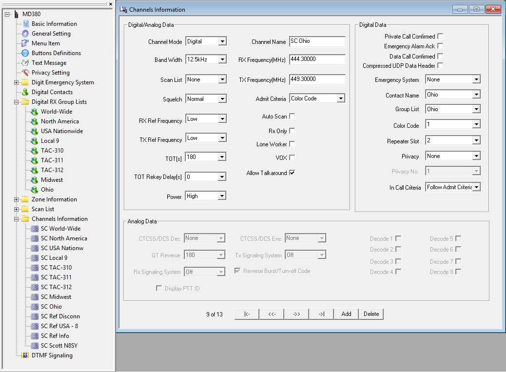
These settings will be applied to every digital channel created for this example and is a good template for actual programming:
Channel Mode: Digital
Band Width: 12.5kHz
TOT[s]: 180s (3 min) max for repeater & hotspot, 600s (10 min) max for simplex channels.
Power: “High” for repeaters & simplex – unless really close, “Low” for hotspots.
Admit Criteria: “Color Code” for repeater, “Channel Free” for hotspot & simplex.
Allow Talkaround: yes
Emergency System: None
Privacy: None
In Call Criteria: “Follow Admit Criteria” for repeater, “Always” for hotspot & simplex.
For this programming example, channels are created in the same order as the repeater listing. In the CPS software, create channels with the listed settings including universal settings above. SC = Some City, Ohio:
Channel #1
Channel Name: SC World-Wide
RX Frequency: 444.300
TX Frequency: 449.300
Contact Name: World-Wide
Group List: World-Wide (or Some City TS1)
Color Code: 1
Repeater Slot: 1
Channel #2
Channel Name: SC North America
RX Frequency: 444.300
TX Frequency: 449.300
Contact Name: North America
Group List: North America (or Some City TS1)
Color Code: 1
Repeater Slot: 1
Channel #3
Channel Name: SC USA Nationw
RX Frequency: 444.300
TX Frequency: 449.300
Contact Name: USA Nationwide
Group List: USA Nationwide (or Some City TS1)
Color Code: 1
Repeater Slot: 1
Channel #4
Channel Name: SC Local 9
RX Frequency: 444.300
TX Frequency: 449.300
Contact Name: Local 9
Group List: Local 9 (or Some City TS2)
Color Code: 1
Repeater Slot: 2
Channel #5
Channel Name: SC TAC-310
RX Frequency: 444.300
TX Frequency: 449.300
Contact Name: TAC-310
Group List: TAC-310 (or Some City TS2)
Color Code: 1
Repeater Slot: 2
Channel #6
Channel Name: SC TAC-311
RX Frequency: 444.300
TX Frequency: 449.300
Contact Name: TAC-311
Group List: TAC-311 (or Some City TS2)
Color Code: 1
Repeater Slot: 2
Channel #7
Channel Name: SC TAC-312
RX Frequency: 444.300
TX Frequency: 449.300
Contact Name: TAC-312
Group List: TAC-312 (or Some City TS2)
Color Code: 1
Repeater Slot: 2
Channel #8
Channel Name: SC Midwest
RX Frequency: 444.300
TX Frequency: 449.300
Contact Name: Midwest
Group List: Midwest (or Some City TS2)
Color Code: 1
Repeater Slot: 2
Channel #9
Channel Name: SC Ohio
RX Frequency: 444.300
TX Frequency: 449.300
Contact Name: Ohio
Group List: Ohio (or Some City TS2)
Color Code: 1
Repeater Slot: 2
Channel #10
Channel Name: SC Ref Disconn
RX Frequency: 444.300
TX Frequency: 449.300
Contact Name: Ref Disconnect
Group List: None
Color Code: 1
Repeater Slot: 2
Channel #11
Channel Name: SC Ref USA – 8
RX Frequency: 444.300
TX Frequency: 449.300
Contact Name: USA – Area 8
Group List: None
Color Code: 1
Repeater Slot: 2
Channel #12
Channel Name: SC Ref Info
RX Frequency: 444.300
TX Frequency: 449.300
Contact Name: Ref Info
Group List: None
Color Code: 1
Repeater Slot: 2
Channel #13
Channel Name: SC Scott N8SY
RX Frequency: 444.300
TX Frequency: 449.300
Contact Name: Scott N8SY
Group List: None
Color Code: 1
Repeater Slot: 2 – though really depends which is available on the repeater.
Zones
To use a Channel on the radio, it needs to be added to a Zone. Zones can contain analog channels too.
Some repeater and c-Bridge owners only made 16 talk groups available on their systems. That’s easy. All 16 go into one zone. Repeaters with more than 16 talk groups must have channels grouped.
Order of channels added to a zone will correspond with the dial position: first added will be position 1, second added will be 2, and so on.
Most use the zone to indicate where the repeater is located. Call signs are not often used because the city provides more detail when selecting an appropriate zone, especially when traveling.
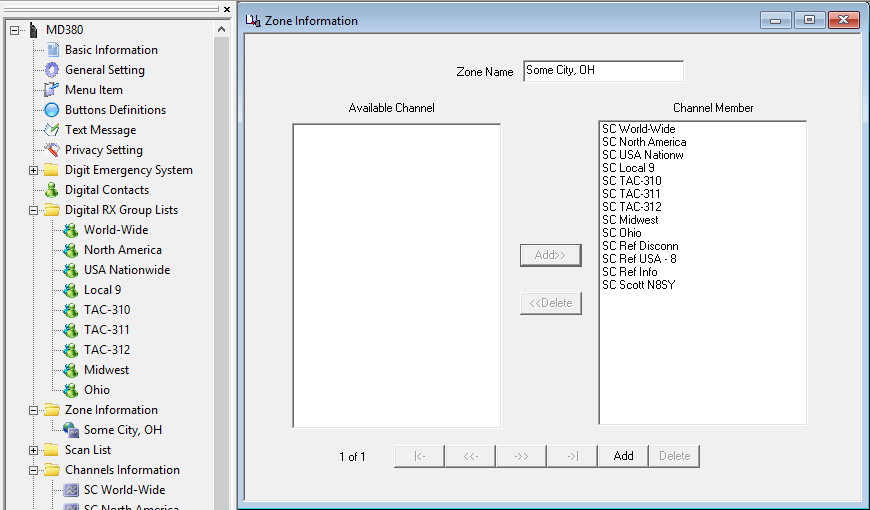
For this programming example, only one zone is utilized. In the CPS software, create a zone with the listed channels:
Zone Information #1
Zone Name: Some City, OH
Available Channel, select and add (position 1): SC World-Wide
Available Channel, select and add (position 2): SC North America
Available Channel, select and add (position 3): SC USA Nationw
Available Channel, select and add (position 4): SC Local 9
Available Channel, select and add (position 5): SC TAC-310
Available Channel, select and add (position 6): SC TAC-311
Available Channel, select and add (position 7): SC TAC-312
Available Channel, select and add (position 8): SC Midwest
Available Channel, select and add (position 9): SC Ohio
Available Channel, select and add (position 10): SC Ref Disconn
Available Channel, select and add (position 11): SC Ref USA – 8
Available Channel, select and add (position 12): SC Ref Status
Available Channel, select and add (position 13): SC Scott N8SY
Scan Lists
Scan Lists are not required for radio operation but are nice for scanner like functionality across repeater time slots and frequencies. Channels have to be established first before it can be added. Scan Lists can contain analog channels too.
Order of channels added to a Scan List will correspond with the scan order. Private Call channels are unnecessary in scan lists because they are infrequent, short, and unnecessarily take up available list entries.
Activating the selected Scan List on the active channel requires assigning the “Scan On/Off” functionality to a programmable button universally in the radio. This is done in “Button Definitions” of the CPS. Another way is to create a channel with the “Auto Scan” feature enabled (see Channels section).
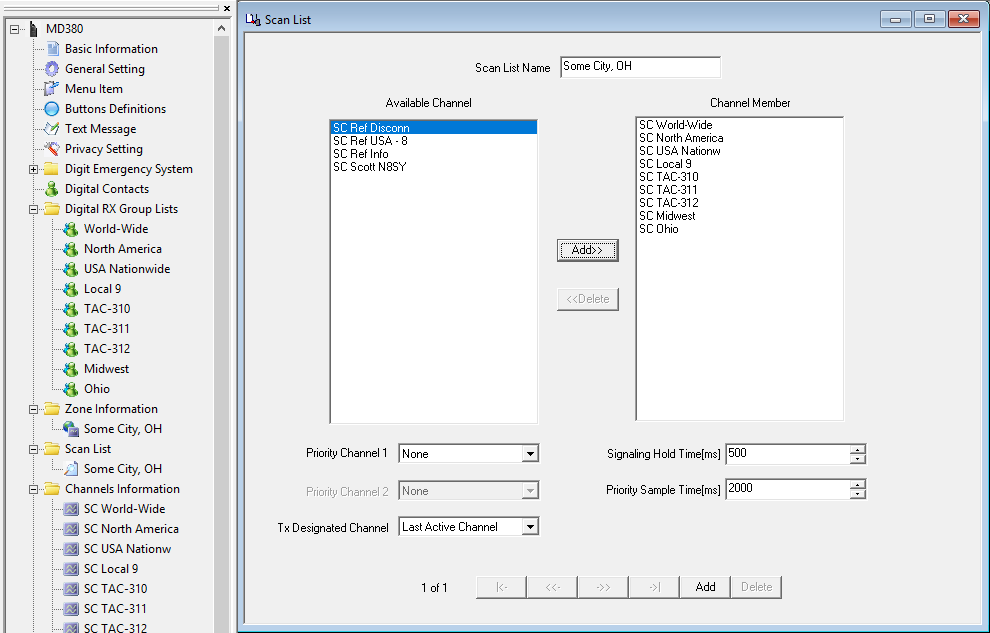
For this programming example, only one Scan List is utilized. In the CPS software, create a Scan List with the listed channels:
Scan List #1
Scan List name: Some City, OH
Available Channel, select and add (position 1): SC World-Wide
Available Channel, select and add (position 2): SC North America
Available Channel, select and add (position 3): SC USA Nationw
Available Channel, select and add (position 4): SC Local 9
Available Channel, select and add (position 5): SC TAC-310
Available Channel, select and add (position 6): SC TAC-311
Available Channel, select and add (position 7): SC TAC-312
Available Channel, select and add (position 8): SC Midwest
Available Channel, select and add (position 9): SC Ohio
Once a Scan List is created, Channels to which a Scan List applies must be updated. All of the “SC” channels.
That’s it! You have successfully programmed a ham radio DMR code plug from scratch! Now, substitute the local repeater’s information and begin having fun!
Suggested talk groups
Here is a suggested list of talk groups to get started on a Brandmeister network U.S. repeater or hotspot. Each bullet can be a separate zone.
Wide area groups (World-Wide: 91, North America: 93, USA – Nationwide: 3100)
Reflectors are different than talk groups. With a talk group, keying automatically establishes the connection and is dropped after 15 minutes. Reflectors must be manually linked and unlinked. Time slot 2 is always used for reflectors and associated commands.
At user discretion, programming can include reflectors of interest. It’s a good idea to program the control commands into a code plug regardless of the desire to use reflectors. A repeater maybe connected to a reflector and left abandoned. Having those commands programmed are good for knocking down an abandoned link.
To establish reflector connection, a private call is made to the reflector ID. Some radios can make on-the-fly private calls by entering the ID on the keypad. Others need a channel programmed with the reflector ID in the “Call ID” field with “Call Type” set to “Private Call.”
A “Group Call” channel programmed to time slot 2, talk group 9 is required to carry on the QSO. This is known as “Local 9” on many repeaters.
When the QSO is finished, another “Private Call” is made to ID 4000 to disconnect the reflector. Private Call to ID 5000 will check the status at any time.
For two stations to establish communication on the “USA – Area 8” reflector (4648), both stations initiate a “Private Call” to ID 4648 on time slot 2, for 2 seconds. Switch their radios to “Local 9” for the QSO. When done, both initiate a private call to 4000 to disconnect their nodes.
Simplex
Like any good communication system, DMR doesn’t have to be operated using a repeater.
Standard DMR simplex configuration and frequencies in the U.S.:
Talk group (contact ID and RX Group): 99
Color Code (channel): 1
Time slot (channel): 1
Admit Criteria (channel): Always (though I like to use “Channel Free”).
In Call Criteria (if applicable, channel): TX or Always.
UHF
441.000
446.500
446.075
433.450
VHF
145.790
145.510
Simplex code plug programming template:
Contact
Contact name: Simplex
Call type: Group call
Call ID: 99
Receive tone: No
Digital RX Group List
Group List Name: Simplex
Available Contact, select and add: Simplex
Channel, common:
Channel Mode: Digital
Band Width: 12.5kHz
TOT[s]: 600s (10 min) max.
Power: High
Admit Criteria: Always
Allow Talkaround: yes
Emergency System: None
Privacy: None
In Call Criteria: Always
Contact Name: Simplex
Group List: Simplex
Color Code: 1
Repeater Slot: 1
Channel 1
Channel Name: Simplex 441.000
RX Frequency: 441.000
TX Frequency: 441.000
Channel 2
Channel Name: Simplex 446.500
RX Frequency: 446.500
TX Frequency: 446.500
Channel 3
Channel Name: Simplex 446.075
RX Frequency: 446.075
TX Frequency: 446.075
Channel 4
Channel Name: Simplex 433.450
RX Frequency: 433.450
TX Frequency: 433.450
Hotspots
Many hotspots follow very similar programming to that of a repeater. Others offer a ‘simple’ mode utilizing a single talk group in the radio to make programming easier. I prefer my hotspot to function like a repeater.
Hotspot devices like the SharkRF OpenSpot and DVMega act similar to a repeater in terms of the programming. Follow the programming tutorial above with differences being the TX frequency would match the RX frequency (simplex) and time slot is always 2 (though the OpenSpot can use either).
For the OpenSpot, every RX Group will need to include “Local 9” to hear the voice announcements from the OpenSpot. These are the ‘connected’ and ‘profile’ announcements. There are additional control commands that can be used with the OpenSpot, like changing profiles, which are outlined in the manual: https://www.sharkrf.com/products/openspot/manual/
The OpenSpot can alternatively operate in a simple mode where transmissions to and from the Internet are routed to and from talk group 9 for the radio. Example: hotspot is connected to talk group 3139, the radio receives and transmits using talk group 9; connected to talk group 3100, radio still uses 9. Using this method, talk group changes have to be made through the OpenSpot web interface including changing the ‘Reroute ID.’
The DV4Mini will ONLY operate using talk group 9. For this reason, programming talk group 3139 into the radio for the DV4Mini will NOT work. No other talk group configuration will work with the DV4Mini EXCEPT talk group 9!
Brandmeister Extended Routing (XTG) is needed for talk groups not listed in the DV4Mini DV4MF2 application (eg: TAC-310, TAC-311, or TAC-312).
A programming example for OpenSpot in ‘simple’ mode or the DV4Mini. 446.900 is the simplex frequency chosen for the hotspot:
Contact (does not need to be created if “Local 9” already exits.)
Contact name: OpenSpot/DV4Mini
Call type: Group call
Call ID: 9
Receive tone: No
Digital RX Group List (does not need to be created if “Local 9” already exits.)
Group List Name: OpenSpot/DV4Mini
Available Contact, select and add: OpenSpot/DV4Mini
Channel
Channel Mode: Digital
Band Width: 12.5kHz
TOT[s]: 180s (3 min) max.
Power: Low
Admit Criteria: Always (though I like to use “Channel Free”).
Allow Talkaround: yes
Emergency System: None
Privacy: None
In Call Criteria: Always
Channel Name: OpenSpot/DV4Mini
RX Frequency: 446.900
TX Frequency: 446.900
Contact Name: OpenSpot/DV4Mini (or Local 9)
Group List: OpenSpot/DV4Mini (or Local 9)
Color Code: 1
Repeater Slot: 2
You’re now setup to use OpenSpot in simple mode or DV4Mini!
Planning on picking up a new DMR radio at Dayton? DMR saw growth due to inexpensive offerings of quality radios at last year’s show. I suspect this year will be no different with new offerings from vendors and many more groups supporting DMR. How many of you know the terminology and could program a radio from scratch?
Passing around a code plug makes the mode seem plug-and-play and it’s a great way to get started. Relying on existing code plugs leaves most of us unable to change the configuration of our own radios. What happens if you need to change programming, add a repeater, the code plug information is old, or wrong?
Here I’ll explain DMR concepts and terminology as it relates to the Ham Radio service. Next, I’ll walk through programming an example repeater and hotspot for devices like the SharkRF OpenSpot, DVMega, and DV4Mini. This series is intended for the beginner to better understand the technology by providing practical reasons and examples. These won’t be tied to a specific radio or repeater though there will be differences between vendors, models, repeaters, networks, and configurations in practice. Consult the repeater owner with specific questions.
About DMR
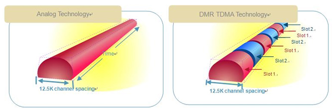
Digital Mobile Radio is an open digital mode standardized by the European Telecommunications Standards Institute (ETSI). It was first published in 2005 and is used in commercial products around the world. Open means the specifications are available for anyone to use, modify, add, or remove features as one sees fit. DMR uses two-slot Time-Division Multiple Access (TDMA) allowing two channels in 12.5 kHz of bandwidth using the AMBE+2 proprietary codec (or vocoder, voice encoder). TDMA is old cellphone technology in use before LTE and GSM. “Spectrum efficiency of 6.25 kHz” is often used which is ‘blah blah’ marketing speak for ‘it really uses 12.5 kHz, half the time.’
ETSI’s objective was to have a low cost, interoperable, digital system. In reality, manufactures added their own proprietary features that make their radios non-interoperable with other manufactures. Motorola’s system is called MotoTRBO which is a DMR capable radio with their own proprietary features. Motorola did not create nor invent DMR but they help bring it to the U.S.
DMR is the first time a commercial system was adopted for ham use. Most of the terms heard in relation to DMR are carryovers from the commercial world. In comparison, D-STAR and Fusion were specifically designed for ham radio use. D-STAR, Fusion, and DMR are all open standards. This means commercial gear is setup for commercial users while ham gear is setup for the way hams use radios. All three use the proprietary AMBE codec allowing 12.5 kHz wide transmissions. DMR achieves two simultaneous transmissions in the same bandwidth. D-STAR uses the AMBE codec while DMR and Fusion use AMBE+2.
D-STAR has an Internet and networking component accessible by users built into the standard. This includes an APRS-like position reporting system called D-PRS. Fusion can transmit pictures messages, and position information to other stations. DMR data features in ham radio are underutilized. Up to this point, text messaging was the most widely used data feature. The Brandmeister network is the first network to begin taking advantage of position reporting data.
Most associate the openness of a standard with how many vendors sell equipment, which is an inaccurate assumption. There have been devices since D-STAR became popular that could turn any analog radio into a digital radio, including repeaters. Now, how much does that equipment cost is the more likely driving popularity factor.
Is it legal?
I hear this issue come up from time-to-time in the Ohio section. I’m sure many more have the same question. DMR is legal (in the U.S.) under Part 97 as of a decision issued on June 9, 2014 by the FCC in docket FCC-14-74. This decision modified Part 97 rules to allow emission types that cover DMR: FXD, FXE, and F7E into Sections 97.3(c) and 97.307(f)(8). Any further questions, please consult an ARRL legal or technical resource.
Keep in mind however, the DMR ID transmitted by the radio IS NOT a legal FCC ID. It’s analogous to kerchunking a repeater without identifying. There must be an identification using voice or something in the data stream must contain the station’s call sign. This includes identifying when linking and unlinking systems. D-STAR and Fusion transmissions contain the call sign in the data stream. Repeaters ID with CW like analog repeaters. The DMR ID in the data stream does not contain a valid FCC call sign and therefore does not constitute valid identification under Part 97. The transmitting station’s name and call sign may appear on your radio display, it still does not make for valid identification. See “Contacts” for more on displayed names and call signs.
Radios, CPS, and Code plugs
Inexpensive DMR radios are easy to come by. There are over 40 manufactures producing DMR equipment. The TYT (Tytera) MD-380 is the most popular ham friendly option for $100 at R & L and Universal Radio – remember to support your local dealers. Connect Systems radios are pricier but come with actual support and a wider selection, including mobiles. The super-cheap Baofeng DMR radios are just like all other Baofengs, crap.
Repurposed radios or new radios that appear on the market will work with the ham radio infrastructure. The radio must cover the appropriate VHF/UHF band and be “DMR Tier II” compliant. DMR Tier I is unlicensed 446 MHz in Europe, similar to FRS. Tier II, aka conventional, is licensed services needing higher power and IP Site Connectivity (IPSC) using the Internet for site linking. Tier III builds on Tier II adding trunking capability and advanced data services.
It’s estimated that 95% of all DMR repeaters in the U.S. are UHF with few VHF. Popular radios are only single band – a commercial carry over because commercial licenses usually cover a single band. Dual band DMR radios should be available by Dayton (2017). In the state of Ohio as of this writing, RepeaterBook is showing 60 DMR repeaters: 3 VHF, one 900 MHz, and the remaining are UHF… so make sure you pick up a UHF model.
To update settings and memories in all DMR radios requires a computer, programming cable, and Computer (or Customer) Programming Software referred to as “CPS.” CPS is the later version of RSS (Radio Service Software) which was used by radio programming professionals and commercial radio resellers. Front Panel Programming (FPP) is a software enabled setting allowing programming via the radio’s front panel. This method allows modification of important programmed functions but not all, so a computer is still required.
The radio utilizes a code plug which is a small program containing radio settings, repeater configurations, Talk Groups, contacts, power outputs, Color Codes, PL tones, signaling methods, and more. A code plug is similar to programming a ham radio with RT Systems or CHIRP. Settings and memories are programmed into the software then downloaded to the radio. Code plug is a Motorola term when physical jumpers were plugged into old radios enabling certain options. Later microprocessor based radios moved the settings internally but the term still stuck referring to radio settings. Today, they resemble small relational databases where settings and data are interrelated and interdependent. Making a change in one area may impact other settings that rely on that data. Next in this series will be programming a sample code plug.
In general, code plugs are radio specific. A TYT MD-380 will work on a MD-390 because the internals are almost identical. However, Connect Systems is not going to work in a Motorola or Hyterra. The newer a radio or less popular a radio is will make it harder to find preprogrammed code plugs.
DMR radios, unless specifically labeled, are not compatible with other ham radio digital systems like D-STAR and Fusion. Advancements are being made to incorporate all digital modes into a single radio by third-party developers.
Registering
Every user on any DMR network requires a CCS7 ID commonly referred to as a “DMR ID” or “radio ID.” CCS stands for “Callsign Communication System” (or Call Connection Service) and is a subscriber identification containing 7 digits. Users registered in Ohio are assigned 3139xxx, where ‘xxx’ is a 3-digit consecutive ID. Ohio used up all 3139xxx IDs and has rolled over to 1139xxx. One might note that the Ohio Statewide Talk Group has the ID 3139! This radio ID has its place on D-STAR, DMR, and Fusion networks but the reasons are beyond introductory level. The CCS7 is a universal ID that will work on any DMR network.
If you don’t already have a DMR ID, follow the instructions on the DMR-MARC registration site [Updated:registration site is now at RadioID] DO NOT REQUEST multiple IDs for a single callsign! Hotspot devices or different radios don’t need separate IDs. Obtaining an ID may take up to 3 days and the process can be started even before buying a radio. If you think you might already have an ID: on the registration page, click the “Database” link, click “User Database,” and search using your call sign (current or previous). To change the registered information for a call sign, use the “Contact Us” link.
Repeaters, c-Bridges, and Networks
In order to program a DMR repeater into a DMR radio, a couple pieces of information about the repeater are needed. To program an analog FM repeater into a ham radio, a user needs the repeater transmit frequency, offset/receive frequency, and PL/DCS tone configuration to access the repeater. Different information is required for a DMR repeater: Color Code and Talk Group configuration is needed. The functionality of a PL/DCS tone is replaced by a “Color Code” (CC) or “Colour” when in Europe. There are 16 possible Color Codes, 0-15. A DMR repeater cannot be Color Code-less. Like PL, the Color Code must match the repeater or the repeater cannot be accessed.
Configuration of the repeater depends on the c-Bridge or network it is connected to. C-Bridge is a communication device to route calls between different networks. There are many ham radio c-Bridges: DMR-MARC, DCI, NATS, CACTUS, K4USD, Crossroads – for example. Some c-Bridges explicitly define repeater configuration, including limiting available Talk Groups only to certain regions. For example, “Rocky Mountain regional” may not be available on Ohio repeaters. Other c-Bridges allow owners leeway in their configuration. User linking is done via Talk Groups or reflectors. Repeaters cannot be linked to directly by other repeaters or hotspots.
Brandmeister is a decentralized network of master servers. Master servers are different from a c-Bridge but an oversimplification is they both provide similar linking functionality. The Brandmeister name is synonymous with DMR but it cross-links with other networks and digital systems like D-STAR and APRS. Work is being done on linking Fusion and P25. All Talk Groups and reflectors on Brandmeister are available to all repeaters and hotspots connected to that network.
As with any linked repeater system, there are significant time delays in fully establishing connections. On an analog repeater system with multiple voted inputs, it will take two or three seconds for the system to fully come up. From the time the radio is keyed, the signal has to reach the inputs, the inputs reach the voter, voter decides which input is the strongest, bring up the transmitter(s), and all receiving stations pick up the repeater’s signal. Fast-keying is one of my pet-peeves where a transmitting station quickly keys their radio and starts talking. Receiving stations only hear the last letter or two of a callsign. Delays are even longer when networking and routing packets is involved over a wide area. This is true for any networked mode: D-STAR, DMR, Fusion, Echolink, AllStar, or IRLP. When first establishing connection on a repeater, first key up for 2 to 3 seconds before saying or doing anything to being up all links. Once links are established, they tend to react quicker so that delay can be dropped to 2 seconds on subsequent transmissions.
Another note when linking DMR systems, at the time a repeater or hotspot is connected, an existing transmission might be taking place on that Talk Group. Nothing would be heard by the station that linked. They think the Talk Group is free and end up disrupting an in progress QSO by calling another station. At the point the system is linked to a Talk Group with a transmission in progress, nothing will be heard until the first station unkeys. After linking, wait a minute while making sure the Talk Group is not already in use before calling.
At some point, you will be ‘bonked’ from a repeater. This is the tone a radio might emit after attempting to access a repeater. There are many reasons for being bonked: repeater didn’t respond because it is offline, wrong Color Code is programmed for the channel, out-of-range of the repeater, an incorrect Talk Group/time slot configuration is programmed, Talk Group doesn’t exist, someone could be making a private call, or there is some other error in the radio configuration. Most likely reason: another Talk Group is in use on the same time slot.
More information about repeaters and time slots is in the “Talk Group” and “Time Slot” sections.
Repeater owners: one big problem with DMR has been the lack of information on your repeater. It’s pointless going through the trouble of putting up a digital repeater and not telling people how to access it. Post the Talk Group layout, how to access them, and include any other procedures users should follow. Post this information on a website, use RepeaterBook or RFinder as both have provisions for listing Talk Groups. It can make all the difference in attracting new users.
Time slot (TS)
Time slots allow two conversations on the same repeater, on the same frequency, happening at the same time, and be completely separate from each other. This is what people refer to when they say ‘DMR is two repeaters in one.’ A time slot can be thought of as a ‘channel.’ Each repeater has two time slots or two channels. A user can only access one time slot at a time. Two Talk Groups cannot be accessed on the same time slot simultaneously.
Each time slot occupies the signal for less than 30ms at a time. Within a 60ms window on a repeater: time slot 1 is transmitted for 27.5ms, then a gap of 2.5ms, time slot 2 is transmitted for 27.5ms, another 2.5ms gap, and then repeats with time slot 1. The human ear cannot detect that small of a gap in audio. A repeater transmits both time slots even though one channel is in use and the other idle. This cuts down on the on/off keying of the repeater. User radios, on the other hand, transmit for 27.5ms each 60ms window. This results in extended life of the handheld battery.
Talk Group (TG)
A way for groups of users to be separated on each time slot, without distracting or disrupting other users, is to use Talk Groups. A commercial example would be a baseball stadium. The ball park might have services like facilities management, guest services, security, first aid, concessions, traffic, and ushers all using the same radio system but the conversations are completely independent. Not all services would be using the frequency at the same time for the entire game. Each radio stays muted until their assigned Talk Group appears on the frequency, then it would unmute or activate for that transmission. Their radios would have the ability to switch over to another Talk Group. Security might need to alert first aid of a guest injury or guest services may need to notify facilities of an issue in one of the suites.
Ham radio Talk Groups can be created for any purpose and usually fall into the categories of wide-area (worldwide), regional (North America, Midwest), or a particular purpose (Ohio Statewide, XYZ club). There can be many Talk Groups available on a repeater time slot. Time slot 1 could have 5 while time slot 2 may have 25. Some c-Bridges organize wide-area Talk Groups on time slot 1 with regional, local, and special use on time slot 2.
Locals are unique and only heard on that repeater, not routed to the network in most cases. Special use includes Parrot and audio test. Parrot repeats received audio by the repeater. Audio test is a Talk Group linked to an online audio meter by the Northern California DMR Group (NorCal DMR). This has been deprecated because Brandmeister Hoseline has an audio meter for each Talk Group. Hoseline lets anyone listen to any Brandmeister Talk Group with a web browser: https://hose.brandmeister.network/. It is the “firehose” of Talk Group traffic.
The larger an area served by a Talk Group, the more repeaters and time slots are tied up simultaneously. Ohio Statewide keys about 60 repeaters at once. Calling and worldwide Talk Groups could be in the thousands and should be thought of as the 146.520 of DMR. Etiquette is to make contact then move to another Talk Group or a reflector. Tactical or TAC Talk Groups are used for longer QSOs and nets as they tie up the least number of repeaters and are selectively linked-up by repeater users.
Repeater configuration includes static Talk Groups – always connected, and dynamic Talk Groups – commonly referred to as PTT (push-to-talk). Dynamic are linked by a user for a period of about 15 minutes. After 15 minutes of no local activity, that Talk Group is dropped and the repeater returns to the static group on that time slot.
C-Bridges and networks tend to keep the same Talk Group numbering (ID) and allow cross-patching to others to keep things consistent. This means Ohio Statewide is the same group and ID on DMR-MARC, DCI, K4USD, Brandmeister, and others.
Brandmeister offers the flexibility for any two radios to key-up on a random Talk Group ID and essentially create their own Talk Group. This can be done using any Brandmeister connected repeater or hotspot. This Talk Group is not hidden or private because it will show up on Hoseline allowing anyone to listen in and any other stations can join in too. A list of known Brandmeister Talk Groups is provided in the links section.
As described in the repeaters section, some c-Bridges severely limit the Talk Groups a repeater can access. What happens when you’re traveling to Florida and want to talk to your buddies back in Ohio? Or worse, talk to a buddy in England? Talk Group options become limited to wide-area ones which tie-up a lot of repeaters for a lengthy QSO. Reflectors are a way to solve this problem.
Similar to D-STAR or IRLP reflectors, nodes are connected in a round-table style configuration. When one station transmits, their signal is transmitted by all other connected nodes. So far, these sound like Talk Groups. The difference is reflectors are available worldwide and repeater users have to specifically link and unlink a reflector. This means only repeaters and hotspots connected to that reflector are tied up during transmissions and not thousands of repeaters on world-wide Talk Groups.
Reflectors are a 4-digit ID that begins with a 4, 4xxx. Not every c-Bridge has granted reflector connectivity. DMR-MARC and Brandmeister have this ability. Some reflectors are cross-patched to Talk Groups on Brandmeister so either the reflector or Talk Group ID can be used. Reflectors are seldom used on Brandmeister because of the availability of all Talk Groups to all repeaters and hotspots on the network. However, reflectors still serve the intended purpose if a station isn’t in range of a Brandmeister repeater.
Contacts
There are three call types in DMR: Group Call, Private Call, and All-Call. Each is a contact within the radio. A Group Call is a transmission from one radio to a group of radios. These instantly link-up dynamic Talk Groups when PTT is pressed. When you press PTT on Ohio Statewide (3139), all other radios configured for 3139 unmute. All-Call is a carryover from commercial and is programed into supervisor radios allowing the ability to make a call to all radios on the same time slot regardless of talk group. All-call is not used in ham radio.
Private Call is a call from one radio to another radio using the other radio ID (see Registering). In ham radio, that ID is associated with an individual. To return a private call, that users’ radio ID must be stored and selected in the radio. These calls are routed to a user’s last known location on the network, like D-STAR call routing. If someone keyed a DMR repeater in Dayton, then travels to Cleveland, the private call is still routed to the Dayton repeater. Private calls are generally discouraged and even disabled on some repeaters. They tie up a time slot and could clobber an existing QSO. Other users will have no idea why they cannot access the time slot. Private calls are acceptable between hotspots because they are lower profile with only a few users. The DV4Mini can receive private calls but didn’t seem to know how to handle returning a private call.
A common issue I hear on DMR all the time is ‘I don’t see your name and call sign on my display. I must be doing something wrong!’ This behavior depends on the contacts stored in the receiving radio. To see the transmitting station’s name or call sign on the radio display, that radio ID must be setup as a contact in the receiving radio. When the radio receives a radio ID in the contact list, the Contact Name is displayed in place of the radio ID. If the radio ID is not in the contact list, the radio displays what it knows which is the seven-digit radio ID that comes across as part of the data stream in the transmission.
The MD-380 for example, has room for 1,000 contacts which is a carryover from commercial. Most police departments and businesses don’t have more than 1,000 radios in their fleet. Ohio has 1,400+ registered users so the MD-380 cannot store all registered users. Modified firmware makes this possible or look for a radio with more memory for contacts.
(Digital) RX Group lists
An RX Group List is a list of Talk Groups that will unmute or activate the radio when received on the same time slot as the current channel. RX lists were created as a way to monitor activity on the repeater regardless of channel. Key thing to remember is these lists are time slot specific. A radio is set to Local9 with Ohio Statewide and Local9 (both on time slot 2) included in the same RX Group list. When a conversation starts up on Ohio Statewide, the radio would unmute even though Local9 is selected. One can turn their radio to Ohio Statewide and join in. These can cause confusion if a station was heard on Ohio Statewide but the reply transmission went out over Local9. Be careful and mindful of the selected channel before transmitting.
If the radio was set to Local9 and a conversation started on North America calling on time slot 1, nothing will happen. The radio would remain muted because the time slot is different – even if they are in the same RX Group list.
As the name implies, these lists only include contacts set to Group Call for their Call Type. Private calls are not included in these because a radio will always unmute when a private call for that radio ID comes over the time slot. RX Groups keep users from interrupting conversations on repeater Talk Groups they are not monitoring. While intended to cut down on interruptions, some will quickly realize they are hearing a lot more Talk Group traffic then they care about.
When a radio does not unmute as a signal is received, the frequency-in-use LED would illuminate or some other ‘in use’ indicator would be seen. This indicates a Talk Group is not in the RX Group list for the channel, another time slot is in use, or a private call is occurring. To scan across time slots and channels, see Scan List.
Channels
This is where it all comes together. Channels are like memory settings of a typical ham radio. These tell the radio which modulation type to use (analog or digital), frequency, time-out-timer setting, power level settings, and scan lists. It ties together DMR specific settings like Color Code, time slot, digital contacts, and RX Groups. Analog channels are programmed here too.
Zones
A Zone is a way of organizing channels. Most radios allow a maximum of 16 channels per zone because that’s how many positions are available on the channel selector knob on top. Channels not included in a zone cannot be selected on the radio. There can be one or many zones per repeater or hotspot. There is no limit to how channels are arranged within a zone.
Zones are selected through the radio’s menu. When a new zone is selected, channels assigned to that zone become positions on the channel selection knob.
An un-programmed position will result in a continuous error-sounding tone from the radio until a valid position is selected. This was probably intended as a notification for commercial users to indicate they are on a channel where no transmissions will be heard, so a continuous tone sounds.
Scan Lists
RX Group lists receive Talk Groups on the same time slot. Scan lists scan different channels. These lists are closely related to the scan functionality of a scanner. Lists can include the different time slots, different frequencies, and include analog channels. Scan lists have a limit of about 32 channels per list. These lists are not required for radio operation.
Roam Lists
Roam lists are similar to when a cell phone switches towers automatically. They are useful when mobile. Though not implemented by many manufactures, the same functionality can be accomplished by creating a Scan List. The scan list would contain a single Talk Group across many repeaters. Roam lists only work well for static Talk Groups. Otherwise, the Talk Group has to be activated on each repeater, essentially defeating the purpose.
Hotspots
Hotspots are low powered (20mW or so) transceiver devices that connect to a network over the Internet. The hotspot becomes the gateway to the network. An Internet connection is required. Some hotspots will require a computer (DV4Mini) or Raspberry Pi (DVMega, DV4Mini) while others are standalone (OpenSpot). Lastly, a transceiver capable of that mode is needed. SharkRF OpenSpot, DVMega, and DV4Mini are all capable of operating D-STAR, DMR, and Fusion. A D-STAR DVAP, for example, would not work with DMR or Fusion.
After trying out the DV4Mini in a number of configurations with different users, the device needs a lot more work. As of this writing, I would personally stay away from it. DVMega’s are good for tinkering or finding a working software image, which can be frustrating. The SharkRF OpenSpot is my recommendation for a hotspot because of stability, ease-of-use, features, and updates.
Communication Examples
Situation: Find any station to make an extended QSO. Solutions: Call out on any Talk Group: this is K8XXX listening on ‘name of the Talk Group.’ Ie: “This is K8JTK listening on Ohio Statewide.” When on a “Calling” Talk Group and contact is made, keep the QSO relatively short, move to another Talk Group (TAC Talk Groups for example) or Reflector for the duration of the QSO.
Situation: Make a sked with a buddy on the same local repeater. Solutions: Use Local9 when all stations are on the same local repeater. Use statewide or other Talk Group when you want to bring in other stations not on the local repeater or hotspot.
Situation: Make a sked with another station on a different repeater. Solutions: Both stations must have both repeaters linked to the same Talk Group or Reflector. Then call the other station as one normally does. For different regions or countries: a common talk group between both repeater networks must be found. Typically, TAC or any Talk Group on Brandmeister.
Situation: Make a sked with a station on a repeater and other on a hotspot. Solutions: Hotspot access is only available on DMR-MARC and Brandmeister networks. A common talk group between the repeater network and hotspot network needs to be used. Typically, statewide, TAC, or any Talk Group on Brandmeister. Both stations must link to the same Talk Group or Reflector. Then call the other station as one normally does.
If you’re still here, you made it through the terminology portion of this series, which is the hardest part. The next will bring it all together as I walk through creating a sample code plug for a DMR repeater and hotspot. DMR has come a long way since I jumped into it at Dayton in 2016. Likely in the next year, explanations here may change slightly and improvements in radio technology may make code plugs unnecessary.