One of the responsibilities of the Technical Coordinator in the Ohio Section is to submit something for the Section Journal. The Section Journal covers Amateur Radio related things happening in and around the ARRL Ohio Section. It is published by the Section Manager Tom – WB8LCD and articles are submitted by cabinet members.
Once my article is published in the Journal, I will also make it available on my site with a link to the published edition.
You can receive the Journal and other Ohio Section news by joining the mailing list Tom has setup. You do not need to be a member of the ARRL, Ohio Section, or even a ham to join the mailing list. Please sign up!
If you are an ARRL member and reside in the Ohio Section, update your mailing preferences to receive Ohio Section news in your inbox. Those residing outside the Ohio section will need to use the mailing list link above. Updating your ARRL profile will deliver news from the section where you reside (if the leadership chooses to use this method).
- Go to www.arrl.org and click the Login button.
- Login
- When logged in successfully, it will say “Hello <Name>” in place of the Login button where <Name> is your name. Click your Name. This will take you to the “My Account” page.
- On the left hand side, under the “Communication” heading (second from the bottom), click Opt In/Out
- To the right of the “Opt In/Out” heading, click Edit
- Check the box next to “Division and Section News.” If it is already checked, you are already receiving the Ohio Section Journal.
- Click Save
- There should now be a green check mark next to “Division and Section News.” You’re all set!
Now without further ado…
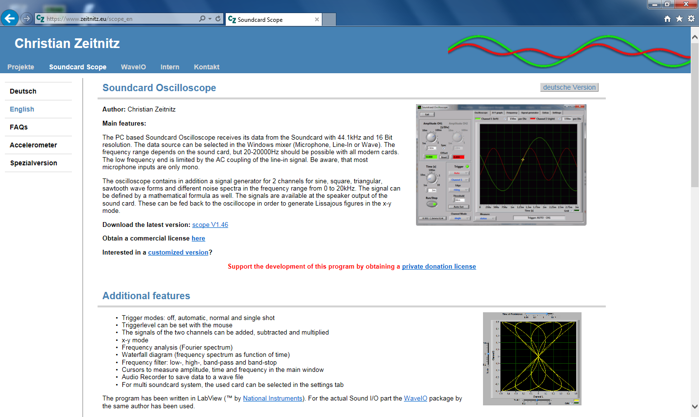
Read the full edition at:
THE TECHNICAL COORDINATOR
Jeff Kopcak – TC
k8jtk@arrl.net
 Hey gang,
I finally did it. What would that be? Over the Christmas holiday, during my time-off, I cleaned and organized the shack. Unseasonably warm weather at the end of December made this job much easier. I don’t know how many years I’ve been threatening to do this. PC problems kicked off the whole cleaning process and I (finally) upgraded to Windows 10. N8SY pointed out: shouldn’t you be upgrading to Windows 11? Yeah, no.
Dust, dead bugs, miscellaneous parts from various projects, all the baggies, twist ties, and boxes are all cleaned up. Using small stackable plastic containers with lids (available at the local superstore) organized computer parts, Raspberry Pi parts, radio cables/accessories, and keep parts of a project together. Some time ago, bought a Power over Ethernet (PoE) network switch from a co-worker. Finally set that up and it’s now powering my Cisco phone used for Hamshack Hotline, Hams over IP, and AmateurWire. In addition, gained more Ethernet ports as those were in short supply.
Parts of the shack were reconfigured. I wanted a spare/second power supply. Astron stopped making their desktop switching supplies with analog meters. I found an SS-30M with analog meters on QRZ and purchased it from a local ham. That supply will be used to power network radios for AllStar Link and Wires-X. An old laptop is put back into service running the Wires-X node, full time. Wires-X was previously running on the same PC I use for operating and I didn’t want to keep that one running all the time.
I did much soul searching in regard to the shack PC. It is coming up on 10 years old. A Micro-ATX PC, Intel Core i5 4th generation (they’re up to 12th gen), 16GB RAM, 128GB SSD, and Windows 7. Due to family commitments and as a result of the shack being declared a disaster (by me), I wasn’t operating much the last 2-3 years. Most of 2022, I operated Winlink making few other contacts.
My intention was to get some operating time over the holidays and didn’t plan to spend that much time redoing things. While operating, quickly remembered ongoing problems with the PC. Cluttered with apps I was testing or no longer used, miscellaneous documents from net reports or drills – these were the least of my problems.
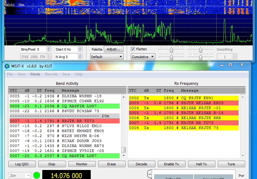
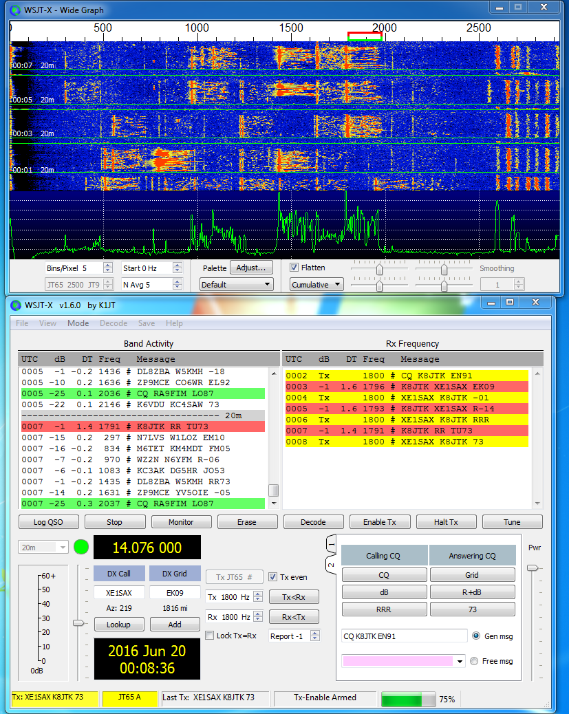
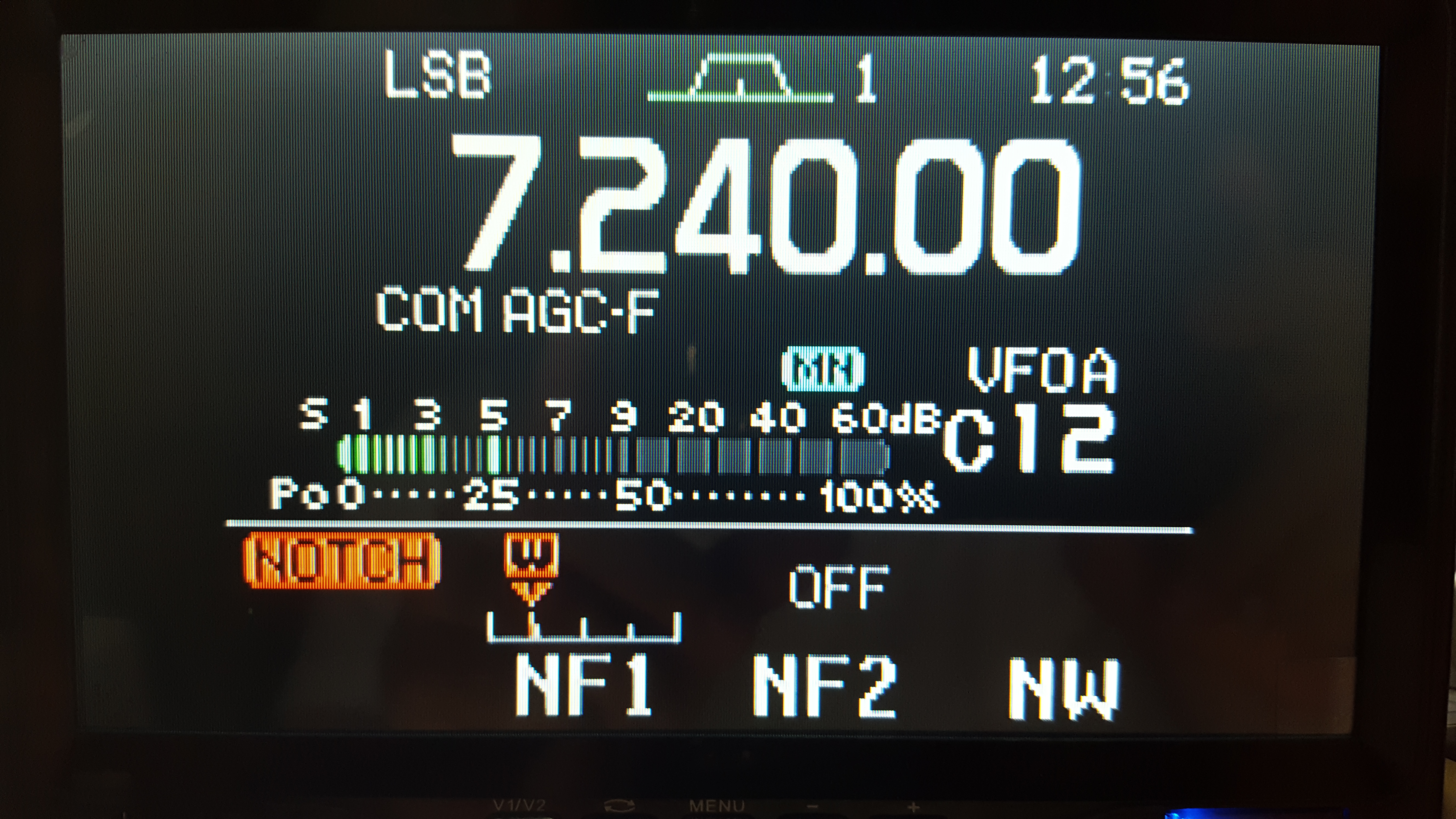
It had serious audio issues. As someone who operates mostly digital on the HF bands, this is incredibly annoying. The Windows audio subsystem, at times, simply failed to start where a red X would be shown over the speaker icon in the system tray. This prevented any audio program from functioning. Rebooting once (or twice) would clear that issue. Random receive cycles in WSJT-X (FT8) would not decode any stations. RX cycles before would decode fine, a number following would also be fine. The waterfall looked OK (not distorted). However, at seemingly random times, there would be 0 decodes. I started to pray that a fresh install would clear these issues.
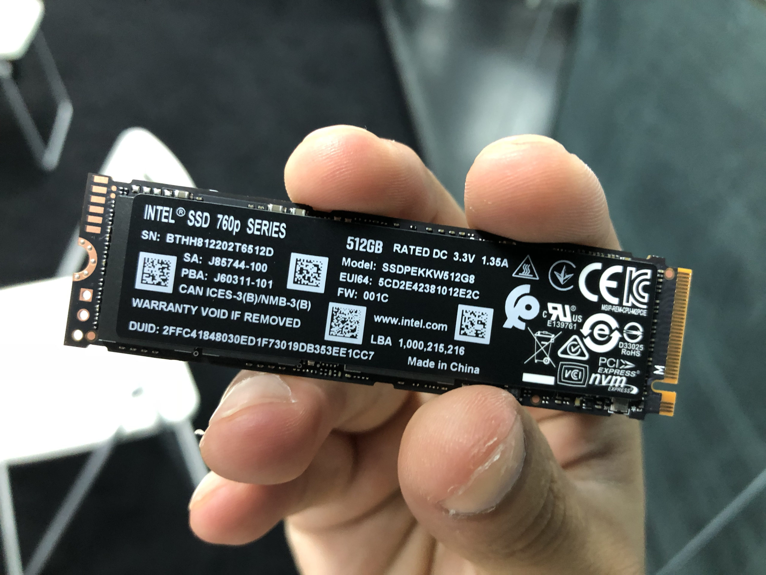
In recent years, I’ve been using smaller desktop form factor computers. Not needing to replace poor included motherboard peripherals (other than graphics cards, separate issue), NVMe M.2 storage (very fast solid-state drive), and use of USB devices, I don’t need many full sized PCs. Included motherboard peripherals, like sound and Ethernet, are very good and don’t need to be substituted with expansion cards as was the case 20 years ago. M.2 SSD storage comes in a very small form factor: 22mm x 30, 42, 60, 80, or 120mm with read/write speeds of 7,000-7,500 MBps. Good 2TB NVMe M.2 storage devices are available for $150.
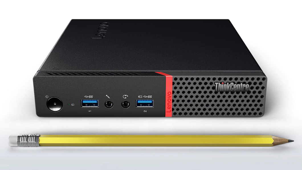
IBM had an excellent reputation for producing solid hardware. That soured a little when they were sold to Lenovo. I’ve had good luck with Lenovo devices at work compared to other vendors. Lenovo’s ThinkCentre PC line are enterprise orientated machines offering mid-to-high specifications. Even though older models have reached end-of-life, Lenovo still releases BIOS updates. In comparison, most vendors release a new motherboard followed by maybe a handful of BIOS updates during its lifecycle. Continued BIOS updates address compatibility problems and patch exploits. I’m impressed their end-of-life PCs are still updated.
I looked at and purchased “renewed” Lenovo ThinkCentre Tiny PCs from Amazon, an M900 & M910Q. Amazon renewed are pre-owned and refurbished PCs resold to keep E-waste down. There are condition guidelines published by Amazon. However, as I found out, quality is left to third-party sellers and varies greatly.
This form factor measures 1.36″ x 7.20″ x 7.05″ weighing in at 1.3 lbs. (M900). Renewed M900 specs: Intel Core i5 6600T, 16GB DDR4 RAM, 512G SSD, Wi-Fi, Bluetooth 4.0, and Windows 10 Pro 64 for $422 (purchased late 2021). M910Q: Intel Core i7-6700T, 32GB RAM, 1TB NVMe SSD, DisplayPort, Wi-Fi, Bluetooth, and Windows 10 Pro was $349 (purchased mid-2022). They’ve come down quite a bit and are now $180 and $274 respectively.
While you get the chassis, motherboard, and CPU (presumably) from Lenovo, everything else is stripped from these renewed PCs. M900 had ADATA SSD and RAM, though a fairly well-known discount name they’re not OEM parts. The M910Q came with a “KingFast” M.2 SSD. That’s right, just KingFast – no model number. The M900 came with a Lenovo branded power supply while the M910Q came with an aftermarket supply that makes an audible sequel when powered. I suspect generates interference, too.
I’ve had issues restoring disk images to the KingFast drive – Acronis complains it can’t read the drive at times. Both included a keyboard and mouse but they are no-name junk. These ThinkCentre’s likely came with Wi-Fi cards from the manufacturer. Those cards are removed and substituted with USB dongles. While I am not using nor did I test any of the dongles, USB dongles for Bluetooth and Wi-Fi are generally bad only working acceptably at short ranges. Additionally, I cannot tell original configurations of these machines because service tags and serial numbers are removed.
Initially purchased these for Homelab projects (virtual machine hosts) and situations where I need a physical Windows machine when a virtual machine wouldn’t cut it. Thought these might be a good replacement for the shack PC. After using them and seeing the poor choice of components, wouldn’t trust these for much of anything. If one desired to go the route of renewed PCs, I would invest in known good replacement parts which adds to the cost. Additionally, the CPUs were only two generations newer than my existing PC. I scrapped the idea of using these or similar “renewed” PCs for my shack.
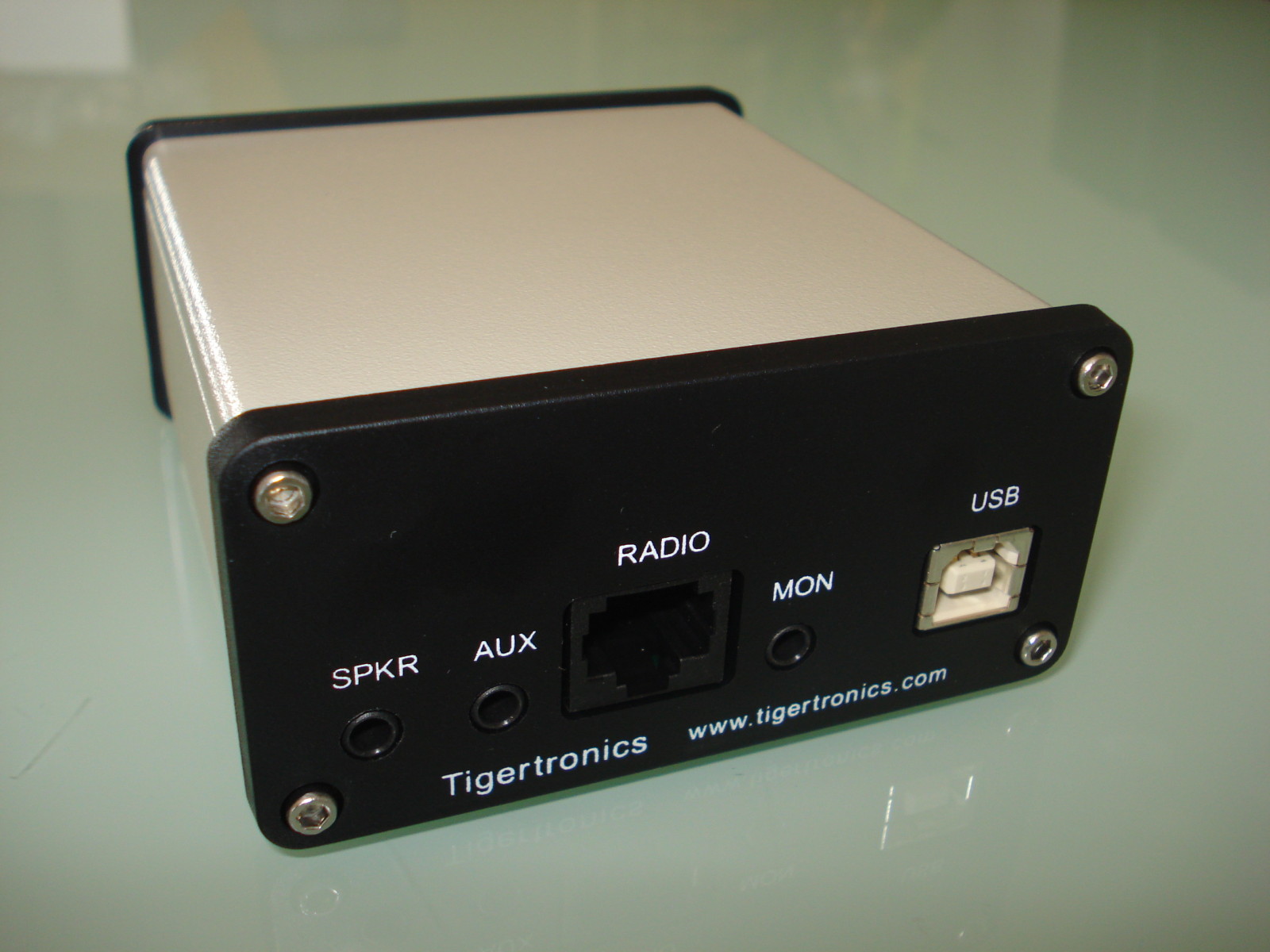
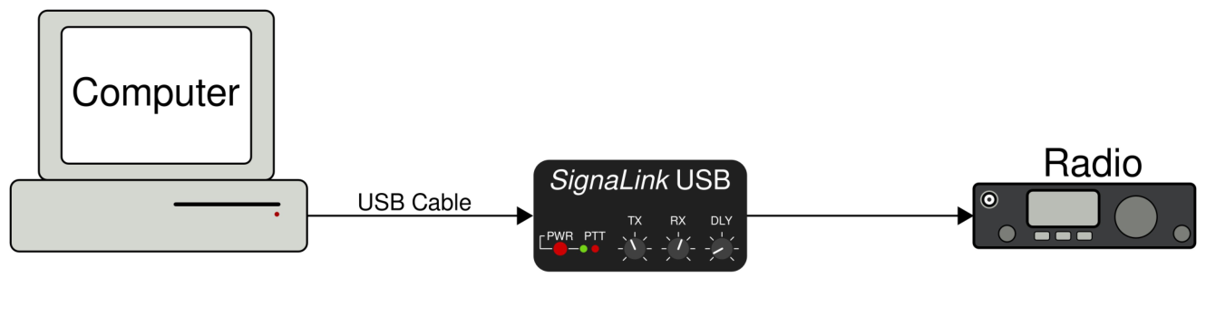
What about new? Brand new machines like these would be great solutions in a car, camper, mobile shack, or boat due to their small form factor. With regard to USB, I need a minimum of six USB ports. While USB specifications and devices are supposed to be compatible, in practice this is rarely the case. To avoid headaches, I require USB cables controlling essential and important components (SignaLink, CI-V, mixers) be plugged directly into USB ports on the motherboard. I only use USB hubs for things I don’t consider essential (radio/scanner programming cables, RTL-SDR dongles). ThinkCentre Tiny PCs have 4 USBs in the back and 2 in the front. That number isn’t going to work for when I want to use additional devices.
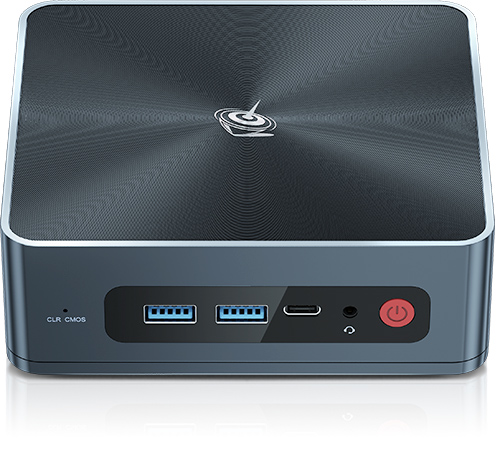
I looked at Intel’s Next Unit of Computing (NUC) offering and mini PCs from BeeLink. They too did not have a sufficient number of USB ports. Using more than one small form-factor PC would be another idea. Unfortunately, don’t have room for another monitor and keyboard. If I ever found a quality keyboard, video, and mouse switch (KVM, or just the K and M), it may solve that. Also, power sources in the shack are becoming scarce. Not to mention current economic issues like higher prices, supply chain issues, shortages, and limited stock. I decided against a new PC until I discover better options or will revisit this when the economy rebounds. HA!
Deciding to keep the same PC, it was wiped and Windows 10 – LTSC installed. No hardware upgrades were performed. There wasn’t much debate for staying with Windows or going to Linux. Programs I use run natively on Windows, such as: radio programmers, scanner programmers, Winlink, Vara, Ham Radio Deluxe, and GridTracker.
Long-Term Servicing Channel (LTSC) is designed to keep the same functionality while not changing operating system features over time. LTSC is a decrapified version of consumer Windows 10, and it’s from Microsoft. It has none of the advertising. No Microsoft Store. No Cortana (virtual assistant). Telemetry still exists based on configuration screens. I used Group Policy Editor and Registry Editor to disable telemetry. A Pi-Hole, or similar, can block tracking at the network level. Consumer support for Windows 10 ends in 2025, LTSC is supported until 2027. Note: people confuse LTSC with the IoT version of Windows 10. This is probably a Microsoft branding issue. They are not the same.
An LTSC license is expensive at $210, or more. Though I did see a China based seller listing them for $19!!? – Caveat Emptor. I purchased through CDW. I’m willing to pay for bloat to be stripped from my Windows operating system. If you don’t want to play the license, that version can be found by doing some digging. I tried a number of the ways to remove bloatware in consumer versions of Windows 10 with programs and random scrips found online in the past. Removed crap often returns as part of “feature updates.” Windows 11 does not yet have an LTSC version and the reason I did not upgrade directly to 11, possibly released later this year.
A clean install of Windows 10 resolved my audio issues and my WSJT-X decode issues are gone as well. On Windows 7, switching between or launching applications would cause hesitation in applications that were running in the background. Opening the browser would cause digital programs to stop transmitting for example. That too is gone in Windows 10. I am happy with the results post upgrade.
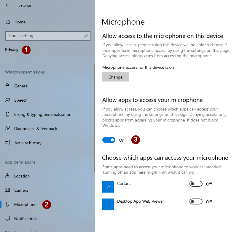
There are some important settings to note in Windows 10 related to ham radio sound card programs. I’m overzealous turning off access to things that don’t need access. Most everything in Settings ? Privacy I have turned off. Doing so prevented ham radio sound card programs from functioning correctly. Programs such as: Echolink, Fldigi, DM780, FreeDV, WSJT-X, Vara, etc., etc., etc. Operating ham radio sound card programs in Windows 10 (and likely 11), Microphone access must remain enabled. Even though none of those programs are listed as accessing the microphone. While labeled Microphone, this setting prevents programs from accessing all sound input devices. These are input devices listed under the Recording tab in Sounds. Programs like SDRs use output from one program as input for TX, a double whammy.
- Close any programs using sound devices
- Go to Start -> Settings -> Privacy (Privacy & security in Windows 11) -> Microphone
- Set “Allow apps to access your microphone” to enabled/on
- Re-open programs that were using audio devices and sources
Sound card digital programs will now work. If there are still issues, move on to troubleshooting audio levels and verify correct audio sources are chosen in the respective program’s settings.
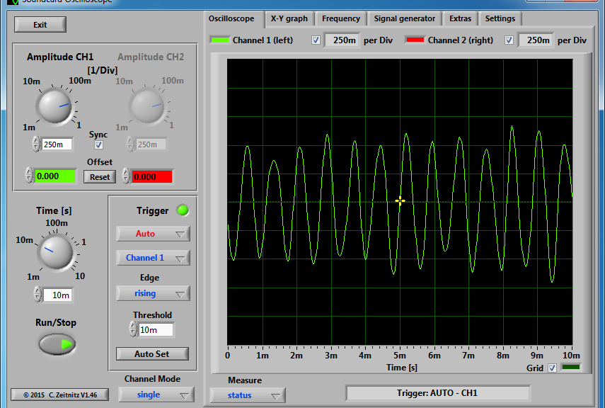
In Windows 7 and my guide for settings levels when using ham radio sound card audio programs, I recommended setting levels to 50%, or half. Some pointed out manufacturers indicated to choose the decibel scale, not the percentage scale I was referring. None of the references said why users should use that scale over percentage. After all, the slider didn’t change switching between the two scales.
After doing some digging and testing, figured it out. Different versions of Windows use different scales – even for the exact same audio device. The 50% setting will likely be different between Windows 7 and Windows 10.
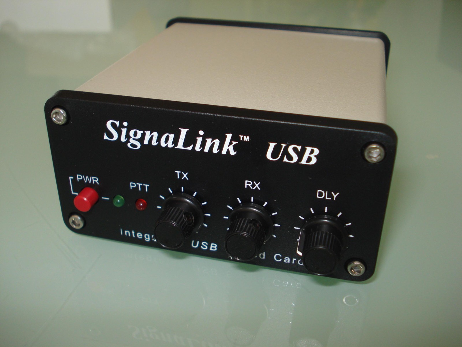
Used my SignaLink to obtain these dB ranges:
- Windows 7 – speaker (transmit audio): -128.0 dB to 0.0 dB
- Windows 7 – microphone (radio receive audio): -192.0 dB to +30.0 dB
- Windows 10 – speaker (transmit audio): -128.0 dB to 0.0 dB
- Windows 10 – microphone (radio receive audio): -96.0 dB to +30.0 dB
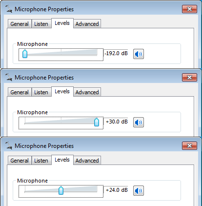
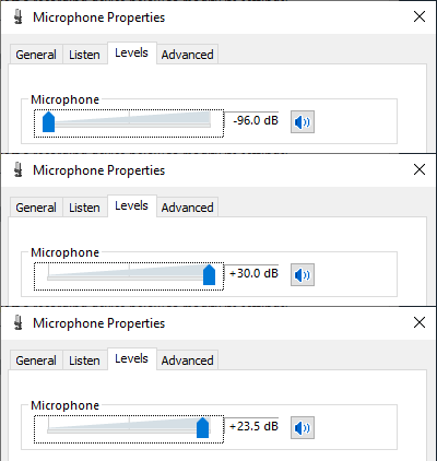
In this case, speaker ranges are identical with -10.5 dB being 50% for both operating system versions. However, microphone input at 50% on Windows 7 is +24.0 dB. On Windows 10, +24.0 dB is roughly 96%. A wide variation and I noticed the level difference right away. Understanding this helped me translate my audio settings from Windows 7 to 10. I did find a Microsoft Learning document explaining Default Audio Volume Settings pointing out the differences in different versions of Windows.
I am very happy the shack is no longer a DMZ. My sound card digital programs are working again and I have a clean desktop install – for now, lol. Haven’t yet been consistently operating due to work and family commitments. When you do find me on the air, I’ll be (likely) logging contacts for Volunteers On The Air.
I would like to formally welcome the newest member of the Technical Specialists group, Ronald – NQ8W. He comes to us with a number of ETA International certifications in electronics, computers, and wireless communication. Ron is a former Master Electrician with degree in Mechanical Drafting. He obtained his GROL and has Emergency Communication certifications. When I talked with Ron a while ago, he was very pleased with the work of our Technical Specialists and wanted to give back with his skills. Welcome to the group!
Speaking of the Specialists. Earlier this month, I was invited to be the guest speaker at the Cuyahoga County ARES meeting. The topic: me, the Ohio Section Technical Coordinator. Not long before I was appointed Technical Specialist, I had no idea there was a technical organization at the section level. After being appointed TC, a group in Columbus asked for me to speak about ‘what does the TC do?’ Out of that came an opportunity to educate hams about the ARRL Field Organization and the work of our Technical Specialists. I had a great time at the Cuyahoga ARES meeting. There was plenty of discussion on technical topics and RFI stories (I cover troubleshooting techniques) after the presentation. If your group would like to know more about the technical and experimentation side of the Ohio Section, send me an E-mail.
Thanks for reading and 73… de Jeff – K8JTK