One of the responsibilities of the Technical Coordinator in the Ohio Section is to submit something for the Section Journal. The Section Journal covers Amateur Radio related things happening in and around the ARRL Ohio Section. It is published by the Section Manager Scott – N8SY and articles are submitted by cabinet members.
Once my article is published in the Journal, I will also make it available on my site with a link to the published edition.
You can receive the Journal and other Ohio Section news by joining the mailing list Scott has setup. You do not need to be a member of the ARRL, Ohio Section, or even a ham to join the mailing list. Please sign up!
If you are an ARRL member and reside in the Ohio Section, update your mailing preferences to receive Ohio Section news in your inbox. Those residing outside the section will need to use the mailing list link above.
Updating your ARRL profile will deliver news from the section where you reside (if the leadership chooses to use this method).
Go to www.arrl.org and logon.
Click Edit your Profile.
You will be taken to the Edit Your Profile page. On the first tab Edit Info, verify your Email address is correct.
Click the Edit Email Subscriptions tab.
Check the News and information from your Division Director and Section Manager box.
Click Save.
Now without further ado…
Read the full edition at: http://n8sy2.blogspot.com/2016/08/august-edition-of-ohio-section-journal.html
THE TECHNICAL COORDINATOR
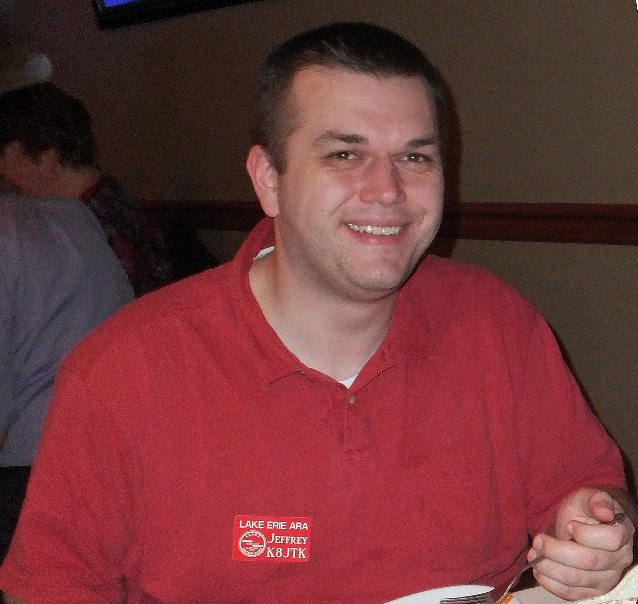
Jeff Kopcak – TC
k8jtk@arrl.net
 Hey Gang,
As I’m beginning this month’s article some nasty storms just ripped through Cleveland on the 11th. There were branches, trees, wires, power lines down, and road closures on the west side due to those hazards, including my QTH of Westlake. Luckily I’ve heard of no injuries. If you’re not part of the NWS Skywarn program, please consider joining as a spotter. Skywarn is a volunteer program that helps the local National Weather Service office know what’s happening on the ground and assists in warning people about dangerous weather conditions. Training typically happens in the early spring for spotters. Check with your local club or Skywarn organization.
The Republican Nation Convention went off without major incident in Cleveland. I was working from home and had the scanner on most of that week. Three major trunked radio systems were utilized: MARCS, the new MARCS-IP (Multi-Agency Radio Communications System), and GCRCN (Greater Cleveland Radio Communications Network). If you didn’t set a wildcard or use UniTrunker to watch those systems, you probably missed a lot of the event communications. There were about 12 primary talk groups on GCRCN where most of the action took place. These were previously unidentified so they were not in any lists or databases that use Radio Reference. A wildcard stops on any talk group whereas programming specific talk groups into the scanner will only stop on transmissions for those talk groups. The “old” MARCS system was shut down immediately following the convention as it was kept online largely for backup. It has been replaced by the MARCS-IP system.
This month we learned the sad news of Hara Arena’s closing. No more Hamvention at Hara Arena after 52 years. The Dayton Amateur Radio Association put into action their contingency plans. It was announced that Hamvention will still be in the Dayton area. The new location is The Greene County Fair and Expo Center located in Xenia, Ohio. Michael Kalter and Ron Cramer talked about the new location on Ham Nation for about 30 minutes in episode 259. Couple of links worth visiting:
-Why we are saddened by the loss of the Hara Arena: http://ad8bc.com/bc/?p=601
-Hamvention Announces Venue for 2017: http://hamvention.org/hamvention-announces-venue-for-2017/
-Ham Nation episode 259: https://twit.tv/shows/ham-nation/episodes/259, or YouTube link: https://www.youtube.com/watch?v=g_OaKmllEDY
One of our Technical Specialists, David KD8TWG, has been involved with setting up a DMR repeater in Cleveland. The frequency is 442.0875 (+5 MHz standard offset) using Color Code 1. The repeater is connected to the K4USD cBridge (http://www.k4usd.org/). On that website is a listing of the “standard ![]() configuration” for repeaters connected to the bridge. Right now, your code plug should follow the layout listed on the site. A cBridge is a feature that allows interconnecting of repeaters over the Internet and a Color Code is equivalent to a PL tone or DCS on analog repeaters.
configuration” for repeaters connected to the bridge. Right now, your code plug should follow the layout listed on the site. A cBridge is a feature that allows interconnecting of repeaters over the Internet and a Color Code is equivalent to a PL tone or DCS on analog repeaters.
When I picked up my DMR radio at Dayton, I found a code plug that had repeaters in Dayton and Columbus for the drive home. It was a nice opportunity to quickly get on the air with DMR but I kept threating myself to write my own. With the installation of the repeater in Cleveland, I took the opportunity to do just that. What is a “code plug?” Some history I found online notes the origins came from wire plugs, later jumpers, which were plugged into the radio to enable certain options or features. Since everything is now processor based, the term continues to stick with the radio world and is a fancy word for ‘radio configuration.’ It contains transmit/receive frequencies, tone selections, timeout values, IDs, configuration settings, etc. I used the one I found in Dayton as a reference. 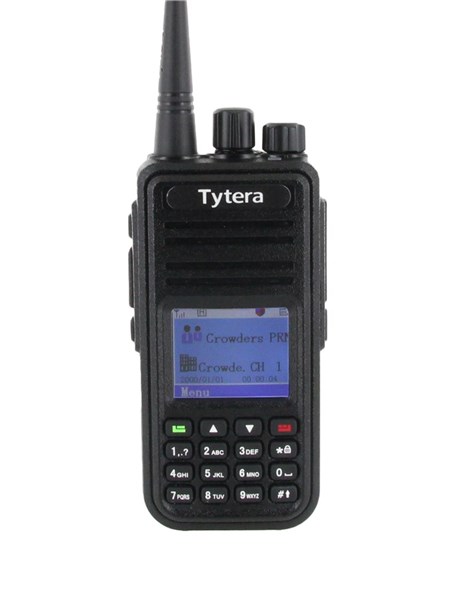 There is also a sample one on K4USD’s site for my radio. I compared the two and designed mine the way I thought worked best. Just because someone designed a code plug one way doesn’t mean you can’t modify or do it differently. It’s analogous to one ham’s memory channels are not the same as another. In the end, it took about 3 hours to make mine! Keep in mind that was a lot of learning and comparing, in addition I programmed all 65 possible talk groups so I don’t have to add them in later. From discussions on the air indications are it took others a few hours as well. But my code plug works! I couldn’t be happier. Well OK I could, apparently I’m just far enough away that my 5 watts doesn’t quite make the trip. I took the radio to work and tested it from there.
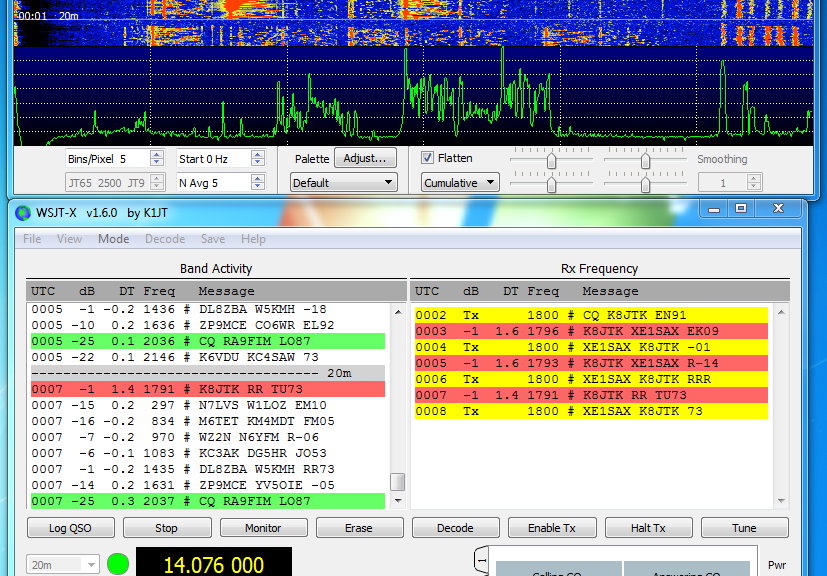
I am writing an introductory series for the Wood County Amateur Radio Club on getting started in digital modes. The first few articles were for those who have never worked digital and want to upgrade their station. Remaining articles will focus on a specific mode. I’ve completed 3 so far (starting in February): an introduction, station setup, and working JT65/9. Published versions can be found at the club’s website 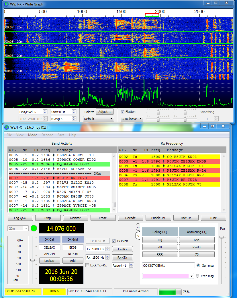 in the CQ Chatter newsletter: http://wcarc.bgsu.edu/. As I point out in the second article, Technician class licensees can still participate. All of these sound card digital modes can be operated over FM simplex or even a net on a repeater using an HT! There are clear downsides like not being able to transmit as far as an HF station and occupying the full 10 to 15 kHz FM, even though the bandwidth of the audio generated by the computer is less. Yes, this defeats the purpose of narrow bandwidth modes. Someone wanting to learn and experiment with these modes may get bitten by the bug and lead to a license upgrade. That’s how I did it. I plan to write an article every 2-3 months.
My dad and I had the opportunity to join the Toledo Mobile Radio Association (TMRA) on August 10. They had Chris Wilson N0CSW, National Sales Manager for Yaesu talk about their System Fusion. Chris did make it clear that the company was paying for travel so there would be some ‘sales pitches.’ The presentation was short but the program ended up being driven by the audience with a lengthy question and answer session. Some things I learned: the DR-2X 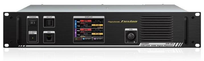 repeater announced at Dayton is not going to be a replacement for the DR-1X, though they may have improved on some shortcomings. The 2X is more of a full featured repeater. It will have the ability to operate dual receive and dual transmit (but not at the same time) creating two repeaters from one unit. They are including voice messaging (like club meeting announcements). Mailboxes were users can record messages for others. This reminds me of the mailboxes repeaters used to have when autopatches were more prevalent. The 2X can monitor a separate control channel for commands. This repeater will not support WiresX but will have “MSRL” (Multi-Site Repeater Linking) via an add-on Ethernet port. Their linking technology will allow the repeater to be linked over any IP based network, including mesh. This brought to mind an interesting use-case where multiple low profile/portable repeaters could be linked at sites with mesh such as air ports, hospitals, and Red Cross shelters. This would create a linked repeater system where not as many users would have to setup cross-banding or run to the other end of a hospital to reach a radio. In contrast, something similar can be done using the AllStar Linking system. At the meeting there was alot of: “I would like this feature/I don’t like this feature in the radio,” “we’re having this problem setting up the repeater to do X” kind of Q&A. My take away from that, their plan is to add features to radios by firmware update and not always release new radios.
In addition to all the work David KD8TWG has been doing to get DMR up and running in Cleveland, he’s been helping repair and upgrade analog repeaters, and setting up APRS IGates around town. He will be giving a presentation on APRS at the Lake Erie Amateur Radio Association’s club meeting on August 30th. Dinner starts at 6:30pm with the meeting at 7:30, don’t need to have dinner to attend the presentation. Haven’t seen an official announcement on location yet but it’s expected to be at the Play Arcade in Mayfield Hts (5900 Mayfield Rd, Mayfield Heights, OH). Check the LEARA website for updates and for dinner reservations: http://www.leara.org/.
 I will be giving my introductory Raspberry Pi presentation at the Cuyahoga Amateur Radio Society meeting, September 13 at 7:30pm. It will be updated as there is new hardware and innovations available. Their meeting location is the Busch Funeral Home, 7501 Ridge Rd, Parma, Ohio. More: http://www.2cars.org/.
Thanks for reading and 73… de Jeff – K8JTK