SSTV
Images via Radio!
Jeffrey Kopcak - K8JTK
Ohio Section Technical Coordinator
Technical Coordinator
The ARRL Technical Coordinator (TC) is a section-level official appointed by the Section Manager to coordinate all technical activities within the section.
Technical Coordinator
Technical Specialist
For a section team to be effective in one of the most important arenas in Amateur Radio, technology, there must be a cadre of qualified, competent Technical Specialists (TS).
"Advancement of the radio art" is a profound obligation we incur under the rules of the FCC.
TSes help meet this obligation.
Technical Specialist
TS supports the TC in two main areas of responsibility:
Radio Frequency Interference and Technical Information.
Technical Specialist can specialize in certain specific technical areas, or can be generalists.
Outline
- About SSTV & History
- SSTV Modes
- Image Comparison
- Signal Analysis
- Software & Modern Interfaces
- Slant
- QSO & Frequencies
- Finding out more
- MMSSTV Tutorial
- LIVE Demo!!!
SSTV...
...stands for Slow-Scan TV.
Transmission and reception of static images
via radio,
in color or black and white.
SSTV...
- Line-by-line progression scanning and transmitting of a single image.
- Downloading images in the dial-up days of the Internet.
- Utilizes 3 KHz bandwidth.
- Transmission length varies depending on mode.
- Considered a digital mode, operated in voice portion of many bands.
- 100% duty cycle on SSB.
In Contrast to...
Though similar names, completely different.
History
- SSTV developed by Copthorne Macdonald (now VY2CM) in 1957.
- In University of Kentucky Engineering Library, came across Bell System Technical Journal about image transmissions using ordinary phone lines.
- Could this be adopted to ham radio?
- Feasibility study to EE Department head, independent study.
- Ordered surplus CRTs and power transformers from surplus houses like Fair Radio Sales in Lima, Ohio.
img: ARRL
History
- Used an electrostatic monitor and vidicon tube.
- Vidicon tube: video camera tube (CRT type).
- Target material is a photoconductor.
- Popular 1970 - 1980.
- Obsolete by CCD and CMOS sensors.
- Early SSTV images... 120 lines, 120 pixels per line.
- Black-and-white.
- 3 kHz of bandwidth.

source & img: Wikipedia
Space Exploration
- SSTV used alot in early space exploration.
- No effective way transmit images to ground stations from spacecrafts.
- Luna 3 was launched in 1959.
- Third space probe sent toward moon.
- First ever photographs from far side of the moon.
- Poor quality images, never-before-seen views of the far side.
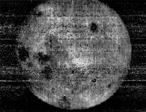
source & img: Wikipedia
Space Exploration
- Vostok 1/Sputnik 5: space dogs Belka and Strelka (10 frames/sec, 100 lines).
- Vostok 2: 400 line resolution.
- Krechet: 2nd generation added overlay data.
- Faith 7 (Mercury-Atlas 9):
1 frame every 2 seconds. - Apollo 7, 8, 9, and 11: 10 frames/sec, 320 lines - TV.
- More like broadcast TV systems.
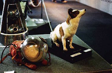
source & img: Wikipedia
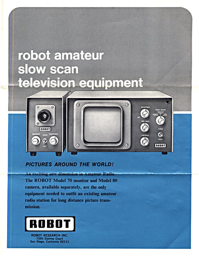
History: '70s
- FCC legalized SSTV for amateur use with an Advanced class license in 1969.
- Required alot of equipment:
-
- Scanner or camera image capture.
- Modem generate/demodulate screeching noise.
- Transmitter/receiver.
- Surplus radar gear displayed image.
- CRT radars had "long persistence" phosphors - image visible for about 10 seconds.
History: 70s - '80s

Modern Systems: '90s - Today
- PC's replaced customized equipment.
- (Image) Scanner, digital cameras, or images from the Internet replaced camera.
- Soundcard with software acts as the modem.
- Computer screen provides the output.
Modes
- B/W, Robot, AVT, Scottie, Martin, SC (Wrasse), PD, P (Pasokon), MP, MR, ML, MP (narrow), MC (narrow).
- Different resolutions.
- Common: 320x256 - 4:3 aspect ratio.
- Different transmission times.
- Longer transmission times, greater clarity on reception.
- Repeater: less than time-out timer (3:00 TOT = 2:30 or less).
Modes
| Use | Mode | Resolution | TX Time |
|---|---|---|---|
| US | Scottie 1 | 320x256 | 1:50 |
| Europe | Martin 1 | 320x256 | 1:54 |
| DX | Scottie DX | 320x256 | 4:29 |
| Quickest TX | B/W 8 | 160x120 | 0:08 |
| Longest TX | P7 | 640x496 | 6:46 |
| Highest Res | PD290 | 800x616 | 4:49 |
As supported by MMSSTV.
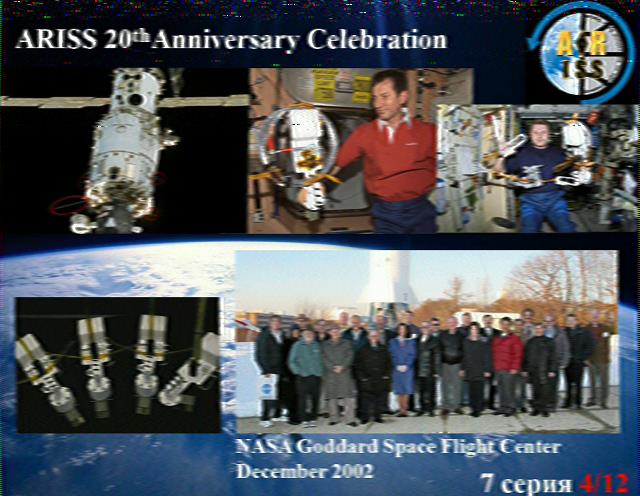
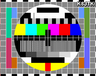
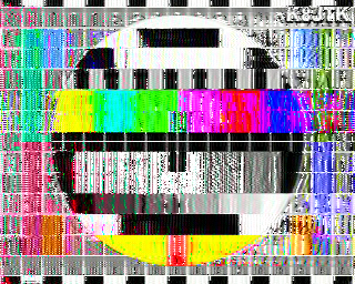
Image Comparison
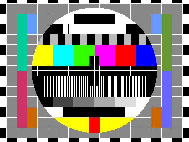
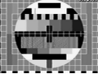
Image Comparison

Image Comparison

Image Comparison
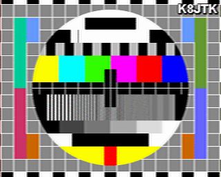
Image Comparison
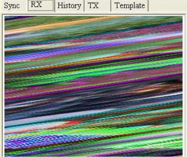
Signal Analysis: Header


SA: Scanlines
SA: Sync

SSTV Software
- Windows PC: MMSSTV.
- Mac: MultiScan 3B, MultiMode (Trialware).
- Linux (and Raspberry Pi): QSSTV.
- Android: DroidSSTV ($6.99).
- iOS: SSTV Slow Scan TV ($2.99) / Ham Radio Decoder Bundle ($6.99).
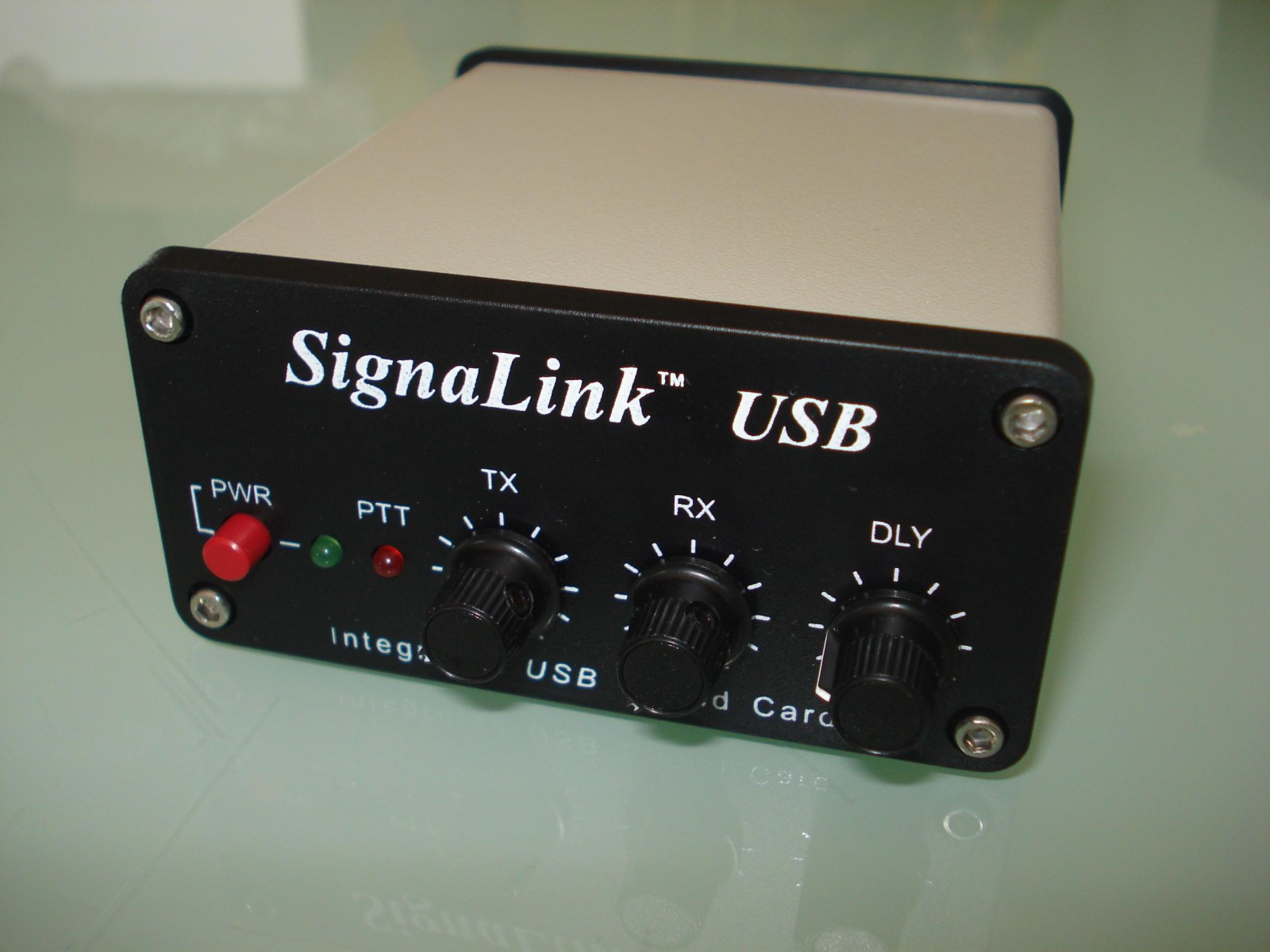
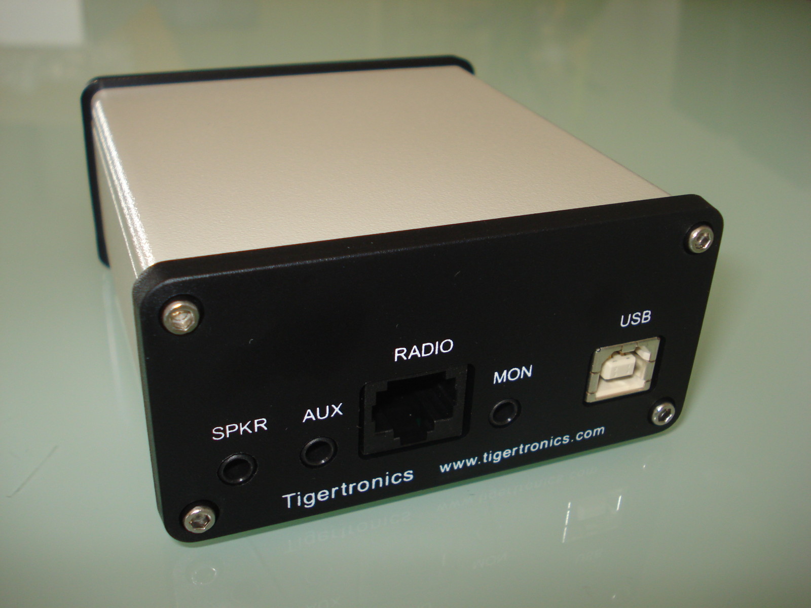
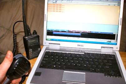
Interfaces
Need a radio, computer, interface between the two, and software.
- SignaLink USB (preferred).
- Rigblaster.
- Built in USB on newer HF radios.
- Build your own connection.
- Acoustic interface.
All audio/DSP enhancements must be disabled!
SignaLink USB

Acoustic Interface
One More
Image Comparison
Interface Quick Tips
- Pet Peeve & PSA (to save you embarrassment): DO NOT leave the sound device as DEFAULT!!!
- Your radio will transmit system sounds, music, screensaver noises, and anything else I send it.
- Set both "Speaker" and "Microphone" volume levels to 50% (half) in Windows. Linux is good to 100%.
- Disable all audio enhancements.
- Test transmission on simplex channel with HT/scanner.
- Detailed setup steps - includes recording and playback methods.
- Advanced calibration.