Tag Archives: Soundcard

Digital Communications in Amateur Radio: JT65 and JT9

This article appeared in the The Wood County Amateur Radio Club newsletter CQ Chatter August 2016 edition.

Read the rest of the series in the Digital Communications in Amateur Radio articles category.


My favorite digital mode has to be the “JTs” otherwise known as JT65 and JT9. Many have equated them to watching paint dry. Others call it the musical mode. I call it my ADD mode. Whatever you call ’em, JT65 has become one of the most popular digital modes second only to PSK. I call it my ADD mode because I can browse the web, watch TV, or write this article during the 7-minute exchange. But you better pay attention because it can still keep you on your toes!

JT65 and JT9 began with Nobel Prize Winner Dr. Joe Taylor – K1JT. One of Dr. Taylor’s passions was weak signal communications and moonbounce (EME). A signal is sent toward the moon at about 1.5 kW on VHF using large directional antenna arrays. The signal is reflected off the moon and received by an equally powerful station with large arrays. After the signal makes the 500,000 mile round trip, there wasn’t much left. CW was the only effective mode. In 2001, K1JT came up with JT65 which allowed hams to make Earth-Moon-Earth contacts with 150 W and 11-element beam antennas. Still not exactly easy but it made EME a possibility for many more hams. Years later it was discovered that JT65 works great on the HF bands too. It allows stations to make contacts without high power or gain antennas. This is perfect for hams that cannot have large or visible antennas. Over time, JT9 was added specifically for the LF, MF, and HF bands (“Work the World with JT65 and JT9”).

It’s not my intention to dive into the technicals of any mode but to give hams practical operating information. When talking about JT65 almost all information applies to JT9 as well. Both are highly time-synchronized. The computer’s clock must be as accurate as possible and within 2 seconds of other stations. One minute transmit and receive sequences are utilized. Transmitting happens within a one-minute window then the roles are reversed for the following minute. Stations begin transmitting 1 second after the beginning of the minute and stop 47.7 seconds later. In the remaining 11.3 seconds applications decode received signals, display them on screen, and receiving stations get their message ready to transmit. The total exchange takes about 7 minutes. More if the message is lost or not decoded. Being such a robust protocol doesn’t leave room for long messages meaning it’s not a conversational mode. The maximum message length is 13 characters with the intent of limiting the exchange to call signs and signal reports. Below is an actual exchange. The first column is the time, second is the exchange, third is the exchange translation. Exchange beings at 01:00 UTC and completes at 01:07. In messages with two call signs, the receiving station is to the left and the transmitting station to the right.

0100 CQ K8JTK EN91
I’m calling CQ from grid square EN91.

0101 K8JTK K5ND EM12
K5ND is returning my CQ from grid square EM12.

0102 K5ND K8JTK -01
I reply to K5ND with his signal report of -1 db (RST Sent).

0103 K8JTK K5ND R-05
K5ND responds with my signal report of -5 db (RST “R”eceived).

0104 K5ND K8JTK RRR
I respond with “roger-roger-roger.”

0105 K8JTK K5ND 73
K5ND responds with best wishes.

0106 K5ND K8JTK 73
I respond with best wishes.

Differences between JT65 & JT9 are bandwidth and signal reports. JT65 takes up just under 180 Hz and about 16 Hz for JT9. JT9 is much better for spectrum efficiency and uses less power due to narrower bandwidth. The JT65 sub-band can often be seen with multiple overlapping signals and they usually decode correctly. JT9 can have ten-times the signals but decoding of overlapping signals is much less likely to happen. Signal reports range from -1 to -30 db signal-to-noise in JT65. The lowest I’ve seen is -27. They are capped at a -1 db upper limit to keep somewhat consistent with EME reports. JT9 is extended to give more accurate signal reports with a range from -50 to +49 db. The limits I’ve seen are -27 and +15. Propagation is comparable between the two modes. JT65 is the overwhelming favorite of operators.

JT65 & JT9 have their own sub-bands. Below is a listing of those frequencies. JT9 is typically 2 kHz above the JT65 frequency. USB is the mode regardless of band.

JT65 JT9
1838 1838
3576 3578
7076 7078
10138 10140
14076 14078
18102 18104
21076 21078
24917 24919
28076 28078
50276 50278

Software is available on all major platforms. Ham Radio Deluxe is expected to include JT65 in the very near future.

Windows:
JT65-HF (http://jt65-hf.sourceforge.net/). It’s very reliable and I’ve only noticed one issue where free hand text doesn’t always transmit. This is the old standard but no longer in development.

JT65-HF-HB9HQX-Edition (http://jt65hfhb9hqxedi.sourceforge.net/). This is the replacement for the above. It’s built on the same code-base so look and feel are similar. The developer has implemented many new useful features. I recommend using this one for newcomers.

Windows/Mac/Linux:
WSJT-X (http://physics.princeton.edu/pulsar/k1jt/wsjtx.html). Software released by K1JT. This seems to give the most accurate signal reports. It’s the only program that currently implements JT9. WSJT-X is the program that I use.

WSJT-X Conversation
WSJT-X application showing QSO with XE1SAX

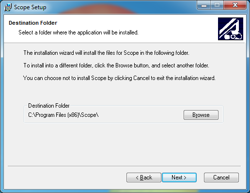
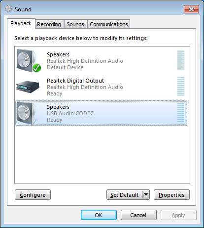
Application setup is fairly straight forward. In the setup, enter your call sign and grid square. If you don’t know your grid square, check QRZ or enter your address on: http://www.levinecentral.com/ham/grid_square.php. Choose the correct sound input/output devices. Configure Rig Control/PTT if needed. Rig Control is not required but helpful when using the internal logging methods.

Before starting any of the applications, ALWAYS sync your computer’s clock with the Internet. In Windows, go to the Control Panel, Date and Time, Internet Time tab, Change settings, click Update now. Most Linux distributions need to invoke ‘ntpdate.’ One feature of the HB9HQX version is automatic time syncing every 15 minutes.

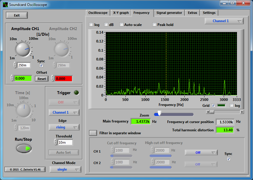
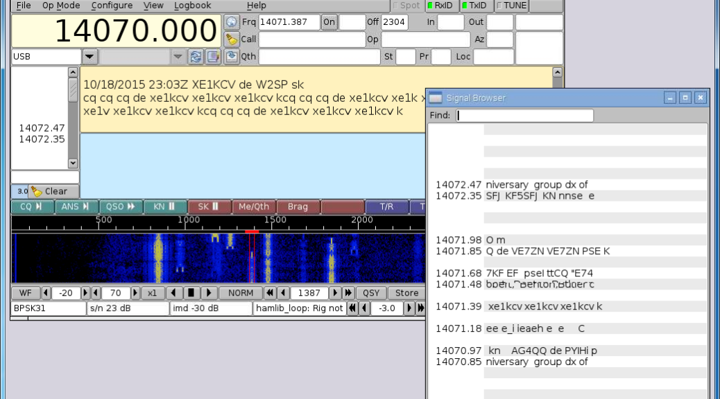
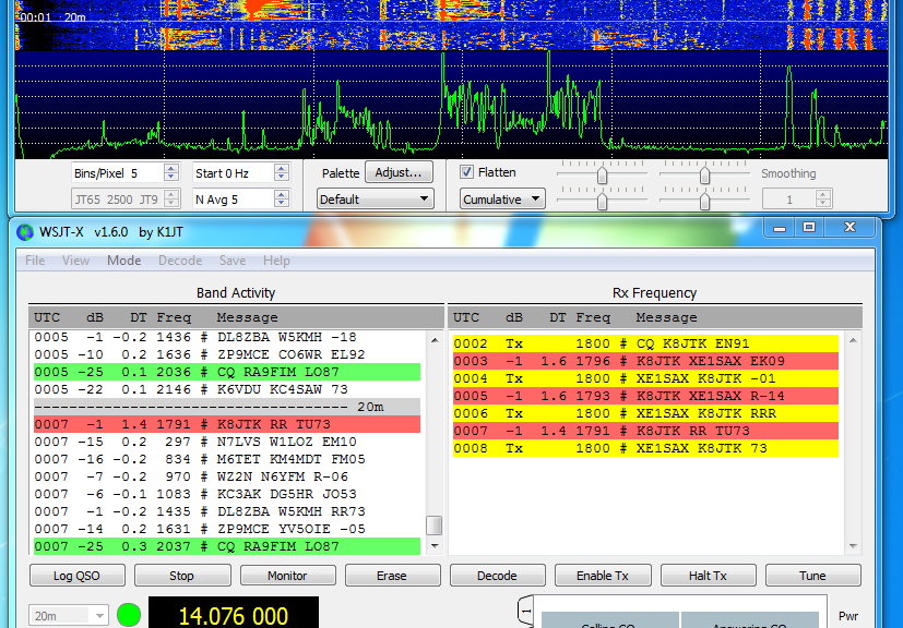
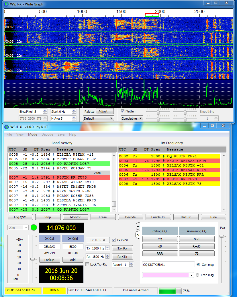
All programs have the same general layout and operate in the same manner. They have a waterfall showing signals received and display markers indicating active transmit and receive windows. These can be moved by clicking on the waterfall.

Conversational buttons and boxes are often labeled Calling CQ and Answering CQ. These buttons automatically generate text during the conversation (following the standard exchange format). Free Text/Message is for free hand text. Other buttons will enable and disable transmitting. Halt will interrupt the transmission midway through. Even/odd indicates which minute you will transmit (only applies to calling CQ). It has no effect when answering a CQ because the software will transmit in the next minute.

The Signal Decoding window is the most important because this is where all conversation exchanges are displayed. A couple labels are seen: UTC – time the signal was decoded, Sync – measurement of the sync signal — higher the better, DT – time difference between decoded station and yours — should be less than 2 seconds, DF – frequency deviation above or below the center point in Hz, and finally the Exchange or Message text. Colors are frequently used to distinguish items of importance. Green is a station calling CQ, red is a message/exchange intended for your station (contains your call sign), gray is exchanges between other stations.

Luckily the software takes care of much of the exchange. It generates response messages by double-clicking a received line. Stations that don’t follow the standard format can easily confuse the software. This is where it will keep you on your toes. If you’re not careful you can end up sending a message twice or not properly advancing to the next message in the exchange. The software does not automatically advance the conversation for you. If things go off the rails, use the appropriate conversational button to get things back on track.

The Free Text field can be used for noting your power, antenna, or sending holiday greetings. These messages are often in place of the 73’s and will not show up in red because no call signs are included. You may see “30W DPL” (I’m running 30 watts into a di-pole antenna), “50W LOOP” (I’m running 50 watts into a loop antenna), “THX 4 NM” (we’ve worked before, thanks for the contact using a new mode from previous contacts), “THX 4NB” (we’ve worked before, thanks for the contact on a new band), “SRY/SRI NO DECODE” (I see a signal on the waterfall but it did not decode) you’ll see this one but it’s not commonly used, “MERRY XMAS” –you get the idea. It’s only 13 characters. Be careful not to baffle the user and you have to be quick. There are some I’ve received that I still have no idea what they mean.

In the JT’s it’s ether a clean decode or nothing at all. No in between. When I see a signal on the waterfall and the message doesn’t decode, I always send my last message again. Some stations will not transmit in the following minute. Other stations (wrongly) move on in the conversation. Then I have to use free hand text to send “SIG RPT?” or similar because I didn’t receive my signal report. At minimum, I make sure RSTs (reliability – strength – tone) have been exchanged and won’t log the contact until “RRR” has been sent/received. Some QSLs I received go as far to log the DF frequency. I’ve only logged the center frequency.

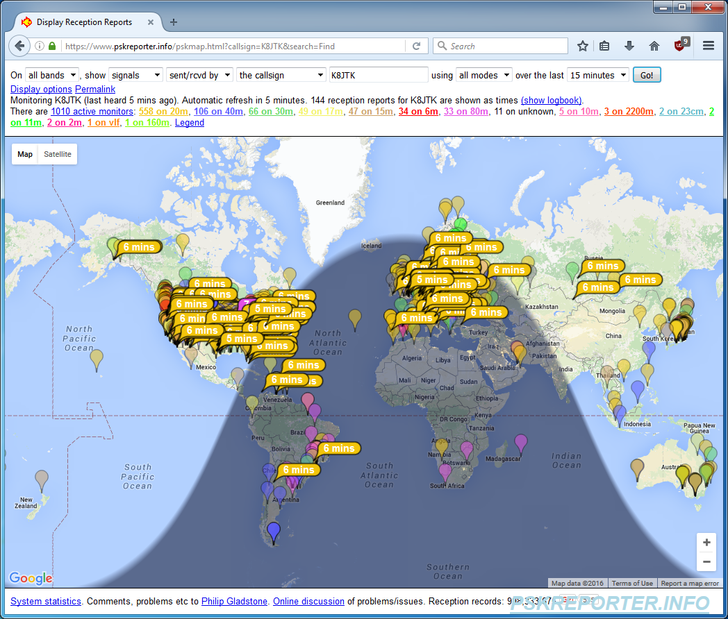
After you feel comfortable monitoring activity, double-click a green “CQ.” The Generated Text field will update with your call sign, their call sign, and your grid square. You’re off! Also, refer back to article two for station/DSP/audio setup. I’ve seen some of the worst over modulated signals on JT65. JT users are really good about uploading spots to PSK Reporter (https://www.pskreporter.info/pskmap.html). You can use it as a ‘reverse beacon’ network to see where your signal is propagating.

PSK Reporter Spots
PSK Reporter application showing received stations worldwide

It’s a lot to take in but an extremely fun mode to work. Find out more information:

Amateur Logic.TV on JT65: https://youtu.be/L7e5NbqhbVU?t=28m10s

QST article: http://www.arrl.org/files/file/Get%20on%20the%20Air%20with%20HF%20Digital/FORD%20JT.pdf

PowerPoint introduction: http://www.arrl.org/files/file/Get%20on%20the%20Air%20with%20HF%20Digital/Getting%20Started%20with%20JT65%20on%20the%20HF%20Bands.pps

“Work the World with JT65 and JT9” book: http://www.arrl.org/shop/Work-the-World-with-JT65-and-JT9/

Use Soundcard Oscilloscope to understand DSP features of an HF radio

As I continue to use Soundcard Oscilloscope in the shack, I find new uses for it.  In a previous post, I showed how to use it to calibrate receive levels for Ham Radio digital modes.  I’ve used Soundcard Oscilloscope to understand DSP (Digital Signal Processing) features of my radio.  I have an ICOM IC-7000 which doesn’t have any of the features the newer/larger radios: waterfall display, frequency display, or oscilloscope.  As a substitute, I’ll fire up Soundcard Oscilloscope to set filters eliminating loud adjacent stations or set a manual notch filter for annoying stations that tune up on frequency.

Soundcard Oscilloscope is a program that emulates an oscilloscope from signal data received from a sound card. It also has a frequency graph which will be used for this tutorial.

Station setup

  • HF Radio and antenna.
  • SignaLink USB and correct cable for your radio (pictures).  Any audio interface will work or even 1/8″ male-to-male audio cable between the audio out of the radio and Line-in on any regular sound card.
  • PC computer where the radio interface is connected.

Program versions

  • Windows 7 – 64 bit
  • Soundcard Oscilloscope 1.46

Download and Installation

This will install Soundcard Oscilloscope on your PC.

hf_dsp_features-01_install-01_soundcard_oscilloscope_website

Go to https://www.zeitnitz.eu/scope_en.

Click the link to “Download the latest version.” Save it in your Downloads folder.

hf_dsp_features-01_install-02_installer-01

Launch the installer.

Click Yes.

hf_dsp_features-01_install-03_installer-02

Click Next.

hf_dsp_features-01_install-04_installer-03

Click Next.

hf_dsp_features-01_install-05_installer-04

Click Next.

hf_dsp_features-01_install-06_installer-05

Installation will begin.

hf_dsp_features-01_install-07_installer-06

Click OK.

hf_dsp_features-01_install-08_installer-07

Click Finish.

Soundcard Oscilloscope is now installed.

Configuration

This will setup Soundcard Oscilloscope to capture audio coming from your audio interface device.

hf_dsp_features-02_configuration-01_language

Start Soundcard Oscilloscope by clicking the Start orb.

Click All Programs.

Click Scope.

Click Scope.

The first time the program is run, you’ll be prompted to select a language. Select your language and click Continue.

hf_dsp_features-02_configuration-02_license

The program is not free and will ask for a License key. Not entering a license will display this screen each time the program is started. The program is less than $12.50 US. Please support the developers by purchasing a license. This is made at the download site by clicking the “private donation license” link.

Click Continue if you don’t have a license.

hf_dsp_features-02_configuration-03_audio_interface_selection

Click the Settings tab.

Under Windows Sound Parameters, Audio Devices, Input is where you select the audio interface device. For SignaLink USB, this would be Microphone USB Audio Codec. Other interfaces: Line In, or Mic In would be selected appropriately and known from my audio interface setup tutorial.

Soundcard Oscilloscope is now configured.

Loud adjacent station

An example using notch functions and filters to remove a loud and stronger adjacent station.

hf_dsp_features-ration-03_loud_adjacent_station-01_settings

Click the Frequency tab.

These settings will need to be reset after restarting the program. At this point, my radio is off but it doesn’t matter.

Along the bottom is the Frequency graph, click about 1500 Hz (1.5 kHz) on the graph.

Slide the Zoom control over about 5 ticks so that the frequency graph now shows 3000 Hz (3 kHz) near the right edge.

I unchecked Auto-scale.  This is not required and only keeps the vertical graph at the same scale for this tutorial.

Turn on the radio if it is not already.

hf_dsp_features-ration-03_loud_adjacent_station-02_loud_station_2500-3200

Between 2500 Hz and 3200 Hz is a strong adjacent station to the frequency I’m trying to work.  The station is really coming in between 2100 Hz and 3200 Hz as we’ll see in a moment.

hf_dsp_features-ration-03_loud_adjacent_station-03_manual_notch_function

I try a Notch Filter (Manual Notch Function – MNF) to notch out the signal.  The wide setting it not enough to get rid of the signal.  The signal is still peaking between 1750 Hz and 3200 Hz.  You can see the notch between 2750 Hz and 2900 Hz.  I tried adding in the 2nd notch filter and it didn’t fully notch out the entire signal.

hf_dsp_features-ration-03_loud_adjacent_station-04_manual_notch_function_radio

Notch filter settings on the 7000 radio.

hf_dsp_features-ration-03_loud_adjacent_station-05_filter

I am able to knock out the loud adjacent station by choosing a narrower filter and using pass band tuning to shift the filter.

hf_dsp_features-ration-03_loud_adjacent_station-06_filter_radio

Turn off the Notch Function.  Selected a filter bandwidth of 1.8 kHz (FIL) (SSB-3 default on the 7000 is 1.8 kHz).  I used pass band tuning (PBT) to shift both edges of the filter to the left (on screen).  In this case the Shift Frequency was -650 narrowing the bandwidth to 1.7 kHz.  The filter shape was SHARP.

These settings eliminated the adjacent station as shown in the previous image.  Everything higher than 2000 Hz is completely gone.

Digital Communications in Amateur Radio: Station Setup

This article appeared in the The Wood County Amateur Radio Club newsletter CQ Chatter May 2016 edition.

Read the rest of the series in the Digital Communications in Amateur Radio articles category.


This time in our quest to get on the air with digital, I’ll discuss station setup. For most of this article, it will be related to HF and sideband operation. I’ll talk about FM near the end.

For a Ham Radio digital setup, three things are needed: a radio, computer, and an interface to connect the two.

First the radio. Theoretically, any radio can be put into digital service. Two things are important to consider: frequency stability and switching speed. Frequency stability is critical to digital operations because drift is deadly. Tube and older radios tend to drift in frequency as they warm up. For a mode such as PSK, drifting a few hertz puts you into someone else’s conversation. Switching speed and fast turnaround times are needed. The switching speed of older radios can be hard on relays. Solid-state radios manufactured in the last two decades are recommended. Radios that cover HF/VHF/UHF all mode – open up even more operating possibilities.

icom_ic-7000_(accessory_&_data_ports)
ICOM IC-7000 rear view showing data and accessory ports.

Most radios are designed with digital modes in mind. Radios with an “accessory port” or “data port” built in are ready to go, though not plug-and-play. The data port is the recommended way to connect an interface to the radio. These ports have pins for keying, transmit audio, and received audio. The audio pins have fixed audio levels and do not change based on the volume setting of the radio. If the radio doesn’t have accessory or data ports, microphone and audio out can be used. It’s not an ideal situation but it will work. An important thing to keep in mind, some radios mix various audio inputs. An example is an external mic connected to the accessory port maybe mixed with audio coming into the data port. This means audio generated by the computer will mix with ambient noise picked up from the microphone. You don’t want this because you’ll interfere with other digital exchanges. It’s important to know your radio and how it operates in different configurations. Test with a buddy or Elmer first before jumping in.

CAT (Computer Aided Transceiver) ports on the radio including RS232 (serial port) and CI-V are useful when creating your own interface. Audio cables between your radio and computer would provide transmit and receive audio but these won’t key the radio. CAT ports provide a lot of functionally including the ability to change settings in the radio, update memory channels, change frequency, etc. Keying the radio via CAT is universally supported in applications. A configuration example would be using the soundcard for audio in/out to the audio out/mic-in on the radio. A separate cable between the computer and radio provides CAT commands, usually via a COM port.

Duty cycle is the amount of time the radio is generating RF. When operating SSB voice, the amount of RF the radio generates depends how loud your voice is at that moment. In CW, RF is generated with each dot and dash. In both cases, the radio is operating at less than 100% duty cycle due to pauses in between words and characters. Many digital modes operate the radio near 100% which causes a lot of heat. Heat causes components to fail. Radios are designed for SSB voice though some newer models are including 100% duty cycle. Operate the radio at a power setting of 50% or less (30% recommended) of the total output power. A 100 watt radio would be set between 30 and 50 watts. FM, by nature, is the exception because voice or digital over FM uses the same bandwidth. The typically longer key down times for digital will still generate more heat.

Radios have different operating modes: USB, LSB, FM, AM, RTTY, DATA, DIGITAL and possibly others. HF digital mostly uses Upper Sideband regardless of frequency. In most cases the USB setting is what you want. Some radios will not allow keying from a computer unless they’re in a ‘digital’ mode setting. Check your operating manual and, again, practice and test with a buddy first. Turn off all filters, blankers, attenuation and the like or set it to the least disruptive setting. Set transmit and receive bandwidths to the full SSB bandwidth allowed (2.8 kHz). No filtering and wide bandwidths have less of a chance to distort or modify the signal. Modification of the signal affects the ability to decode a signal. Filtering can be used but after practice and understanding how they affect decoding. Contests usually warrant filtering to keep loud adjacent signals from affecting the exchange.

The interface. It serves two main purposes: act as a modem and the device that keys the radio. It acts like a modem by taking modulated audio from the software application and sending to the radio for transmit and taking received audio from the radio and sending it to the application for demodulation. Nearly all computers and laptops in the last decade have on-board audio while older configurations utilize an addon soundcard. Most computers don’t have serial ports these days. If a serial port is needed for CAT, options such as a USB (Universal Serial Bus) to serial adapter, serial port addon cards, or cables manufactured with USB to serial adapters built in are available.

rigbaster_advantage
RIGblaster interface–front view.

All-in-one interface solutions make the connection between the radio and computer easy. Solutions offer a built in sound card and fewer cables needed to make the connections. Offerings include products from West Mountain Radio, MFJ, MicroHAM, or RigExpert. These options free your on-board soundcard to listen to music or surf online minimizing the possibility of transmitting audio not suited for the airwaves. Adjustments on these interfaces are audio levels and speed (delay) at which the interfaces switches the radio from transmit to receive. Newer models include all functionality integrated into a single USB port requiring only one cable.

signalink_front
SignaLink USB interface–front view.

The recommended solution for a radio without integrated USB audio is the Tigertronics SignaLink USB. Two cables are needed to make all connections. A USB cable connects the computer and SignaLink for the audio (soundcard) and a cable to the radio for audio and keying. The cable for the radio is specific to connector type or manufacturer. A list of cables is available and simple internal wiring diagram to match the cable to the radio.

signalink_back
SignaLink USB interface–rear view.

Unterminated cables are available to create custom solutions. The SignaLink and cable are about $120 and available at all ham radio retailers. It is a simple VOX (“voice” operated switch) device. When sufficient audio is generated by the computer it keys the radio. It unkeys the radio when that audio has fallen below a threshold.

signalink_diagram
SignaLink USB connection set up.

If you have an interface or are setting one up for the first time, I wrote a tutorial on configuring the interface in Windows. It shows setting default devices and audio levels. These settings help avoid splattering on the bands (taking up more bandwidth than intended) due to too much audio fed into the transmitter. Again, practice with a buddy or Elmer to verify optimal audio settings. Included is a section showing how to record digital transmissions and play them back for decoding at a later time (time shift) such as a net: http://www.k8jtk.org/2015/04/16/radio-interface-setup-for-getting-started-with-ham-radio-sound-card-digital-modes/

The computer. Aside from the requirements to make connections, most computers work fine for digital operation. Ones made within the last decade seem to work without issue. Some older ones tend to have issues. A computer with a 1.5 GHz CPU and 4GB of RAM is sufficient. As always, more is better. Windows is the operating system of choice for digital programs. Mac and Linux are well represented with a program or two less viable than their Windows counterparts. Let’s not forget portable devices like tablets and smartphones. Digital applications are available for those devices too. My operating has been on a Windows 7 64 bit desktop computer.

Up to this point I’ve talked about operating digital on HF and Sideband. What about Technicians who don’t have access to digital portions of the HF bands? All of these digital modes can be operated over FM so you Technicians can get in on the fun too. Won’t be able to transmit as far as an HF station but digital can be transmitted over simplex or even a net on a repeater using an HT! On HF, audio tones are generated by Audio Frequency Shift Keying (AFSK). Audio generated by the computer is converted into RF frequencies when transmitted. Only those frequencies in use at that time are transmitted by the radio. This allows hundreds of exchanges to take place on the same frequency. FM on the other hand occupies the full 10 to 15 kHz, even though the bandwidth of the audio generated by the computer is less. So it still stands only one transmitting station can have the frequency at a time. Yes, this defeats the purpose of narrow bandwidth modes. Someone wanting to learn and experiment with these modes may get bitten by the bug and lead to a license upgrade. I say let them have at it. That’s how I did it.

To this point, Stephen Cass – KB1WNR, Senior Editor for the IEEE magazine built a low power FM digital transmitter for just that reason, get more people interested in digital. It’s a great maker project or demonstration tool for digital. I also mention it because he used my instructions to get Fldigi running on the Raspberry Pi! http://spectrum.ieee.org/geek-life/hands-on/hands-on-a-ham-radio-for-makers

Next time, I’ll start covering specific digital modes, software, and operation.

Images: F8DZY, W3YJ, West Mountain Radio.

Calibrate Receive Audio for Ham Radio Soundcard Digital Modes

This tutorial will show to determine an optimal Receive Volume (RX) level on your audio interface for operating (or only receiving) digital modes.  My tutorial showing how to setup your audio interface in Windows is the starting point for this tutorial.  Please review it, specifically the “Recording” settings as this tutorial builds upon it including having an existing audio interface setup.

The audio level from the radio into the audio interface is typically a fixed level.  Once the audio enters the audio interface, the level sent to the computer is adjustable by the RX or Receive Level controls.  This tutorial will help determine the optimal setting for the RX level.

Soundcard Oscilloscope is a program that emulates an oscilloscope from signal data received from a sound card.  The radio will need to monitor active digital transmissions.  Tuning to HF frequencies where PSK31 (7.070/14.070), JT65 (7.076/14.076), or RTTY (7.080-7.125/14.080-14.100) transmissions can be observed are great places.  The 40 and 20 meter frequencies for those are listed as those bands are more active.

This tutorial can help set the transmit level of another station by observing or monitoring their transmissions.  Do this only after you’ve calibrated your receive audio and spent a good amount of time operating with no audio issues of your own.  Use a quiet simplex frequency both can hear the other station.  This way adjustments will not be effected by other stations on the same sideband frequency.  FM won’t matter because only one station can occupy the frequency at a time.

A similar tutorial appeared in QST recently.  They beat me to it, lol!

Program versions

  • Windows 7 – 64 bit
  • Soundcard Oscilloscope 1.46

Download and Installation

This will install Soundcard Oscilloscope on your PC.

receive_level_calibration-01_install-01_soundcard_oscilloscope_website

Go to https://www.zeitnitz.eu/scope_en.

Click the link to “Download the latest version.”  Save it in your Downloads folder.

receive_level_calibration-01_install-02_installer-01

Launch the installer.

Click Yes.

receive_level_calibration-01_install-03_installer-02

Click Next.

receive_level_calibration-01_install-04_installer-03

Click Next.

receive_level_calibration-01_install-05_installer-04

Click Next.

receive_level_calibration-01_install-06_installer-05

Installation will begin.

receive_level_calibration-01_install-07_installer-06

Click OK.

receive_level_calibration-01_install-08_installer-07

Click Finish.

Soundcard Oscilloscope is now installed.

Configuration

This will setup Soundcard Oscilloscope to capture audio coming from your audio interface device.

receive_level_calibration-02_configuration-01_language

Start Soundcard Oscilloscope by clicking the Start orb.

Click All Programs.

Click Scope.

Click Scope.

The first time the program is run, you’ll be prompted to select a language.  Select your language and click Continue.

receive_level_calibration-02_configuration-02_license

The program is not free and will ask for a License key.  Not entering a license will display this screen each time the program is started.  The program is less than $12.50 US.  Please support the developers by purchasing a license.  This is made at the download site by clicking the “private donation license” link.

Click Continue if you don’t have a license.

receive_level_calibration-02_configuration-03_audio_interface_selection

Click the Settings tab.

Under Windows Sound Parameters, Audio Devices, Input is where you select the audio interface device.  For SignaLink USB, this would be Microphone USB Audio Codec.  Other interfaces: Line In, or Mic In would be selected appropriately and known from my audio interface setup tutorial.

Soundcard Oscilloscope is now configured.

Setting receive level audio

These screenshots will help determine optimal audio RX setting for receive audio.  It is important to leave the audio level settings alone in Windows.  These settings were shown in my audio interface setup tutorial.  Adjust the settings in Windows ONLY when where is not enough audio when RX level is at the maximum setting or there is too much audio with RX set to the lowest setting.

receive_level_calibration-03_calibration-01_settings

Click the Oscilloscope tab if you are not there already.

These settings will need to be reset after restarting the program.  At this point, my radio is off but it doesn’t matter.

Set the Amplitude to 250mv.

Set Time to 10ms or less.

Turn on the radio if it is not already.

Examples

Adjust the RX level until there are no peaks with flat-tops on the oscilloscope.  Flat-tops indicate the audio level is too high and digital programs will have a hard time decoding the signal.  These examples were taking monitoring PSK31 on 20 meters.

receive_level_calibration-03_calibration-02_best_example

This is the best example.  No flat-top peaks.  Peaks appear about two divisions from the center line.  There is plenty of headroom for louder signals.  My RX setting was about the 10 o’clock tick-mark on my SignaLink.

Anything lower than two divisions will still work.  There maybe issues pulling out weaker stations.

receive_level_calibration-03_calibration-03_ok_example

Here is a good example but I would not be comfortable with this audio level.  The peaks do not have flat-tops which is good.  However, the peaks are reaching well into the third division.  My RX setting was about the 11 o’clock tick-mark on my SignaLink.

receive_level_calibration-03_calibration-04_bad_example

This is an example of what the scope should not look like.  Peaks have flat-tops at the fourth division.  The audio level is too high into the computer and RX volume needs to be dialed back.  My RX setting was about the 1 o’clock tick-mark on my SignaLink.

When optimal level is reached, the audio interface receive audio level is calibrated!

Ohio Section Journal – The Technical Coordinator – November 2015 edition

One of the responsibilities of the Technical Coordinator in the Ohio Section is to submit something for the Section Journal. The Section Journal covers Amateur Radio related things happening in and around the ARRL Ohio Section. It is published by the Section Manager Scott – N8SY and articles are submitted by cabinet members.

Once my article is published in the Journal, I will also make it available on my site with a link to the published edition.

You can receive the Journal and other Ohio Section news by joining the mailing list Scott has setup. You do not need to be a member of the ARRL, Ohio Section, or even a ham to join the mailing list. Please sign up!

If you are an ARRL member and reside in the Ohio Section, update your mailing preferences to receive Ohio Section news in your inbox.  Those residing outside the section will need to use the mailing list link above.
Updating your ARRL profile will deliver news from the section where you reside (if the leadership chooses to use this method).
Go to www.arrl.org and logon.
Click Edit your Profile.
You will be taken to the Edit Your Profile page. On the first tab Edit Info, verify your Email address is correct.
Click the Edit Email Subscriptions tab.
Check the News and information from your Division Director and Section Manager box.
Click Save.

Now without further ado…


Read the full edition at: http://n8sy2.blogspot.com/2015/11/november-edition-of-ohio-section-journal.html

THE TECHNICAL COORDINATOR
Jeff Kopcak – TC
k8jtk@arrl.net

DSCF5081 K8JTKHey Gang,

During the State Emergency Test (SET), the Medina ARES group had some issues getting Fldigi working correctly. Not because they didn’t know what they were doing but because when you use Fldigi once or twice a year, you forget what to do. I got an email wanting to know if I would develop a training session on NBEMS standards using Flgidi and Flmsg.

NBEMS stands for Narrow Band Emergency Messaging System (or Software, depending who you ask). It is a set of standards developed to define passing email and text-based traffic over Amateur Radio. We have many digital modes available to us. The VHF/UHF standard is MT63. MT63 is a sufficiently robust mode to deal with background noise and poor band conditions. This doesn’t mean you can have a party at your station and still send MT63 messages but it does well with ambient noise. In contrast, HF NBEMS uses Olivia.

This request was right up my alley as I love to operate digital, educate other hams, and help them get on the air. Much of my time this month was dedicated to putting together a presentation covering: digital communication, use case in Emcomm situations, interfacing options, talking about the Fldigi and Flmsg programs used, setting them up, and workflow.

We though this training might be useful to the section so we invited the leadership. Stan N8BHL and Scott N8SY came. There were County Emergency Coordinators (ECs) who were also in attendance. No pressure. We had a lot of people who wanted to learn about NBEMS, Fldigi, and the capabilities we have. After the presentation, we did hands-on demonstrations with Dave NF8O, Bob K8MD, and Fred K8FH as instructors and transmitting stations so students could see transmitting and receiving all in one place. A lot of great questions and discussion was had. Thank you to the instructors and everyone for coming out! The presentation is available: http://www.k8jtk.org/2015/11/10/vhfuhf-nbems-an-introduction-using-fldigi-and-flmsg-presentations/.

DoboyOne of my points during the presentation was always practice with these technologies BEFORE you need use them. Do a class for beginners. Have the students bring their setup –laptops, go-boxes, radio interfaces, and radios. Find some space to hold the class –EOC/EMA building, restaurant, or library. Then walk through the whole nine yards –installing the applications, setting up Windows audio, setting up the applications, and demonstrate the various tasks they would need to perform. Additional instructors who can assist students or send example transmissions (prepare these ahead of time) should be available. Have the students participate by transmitting messages. This will get them more comfortable and it’s easier to troubleshoot on-site than over-the-air. Make plans for some on-the-air meetings to practice ahead of a test or drill. Meet for an hour or so for a couple weeks until everyone is comfortable.

In Cleveland on Thursday nights, I assist with the LEARA Digital Practice Net on the 146.880/R at 9PM (you don’t have to be a member to participate). The net will operate Fldigi for a number of weeks and switch to SSTV for a time. Our net even ran a simulation drill with ICS forms and everything! Turned out to be a HUGE hit. I wrote up some tutorials for our net. They include: getting your radio interface setup with optimal settings, how to use MMSSTV, Fldigi, Flmsg, and Flwrap. The Fldigi suite tutorials are mostly written to FM NBEMS standards. Links are at the end of this article.

signalinkThe OHDEN (Ohio Digital Emergency Net) is on Tuesdays at 8:00pm. 3.585 USB. The net uses OLIVIA 8/500 with PSK31 as an alternate. They do not run voice on this net which might be unusual for some. All checkins and announcements are done using Olivia. More info: www.ohden.org

I encourage groups throughout the Section to start their own digital practice nets on FM, HF, or both! The tutorials are available to modify to fit your net. These are great opportunities to help hams become familiar and knowledgeable about their digital equipment. Do make sure you obtain permission from the repeater Trustee if you plan to use any repeater. If you do have a digital practice net that originates from the Ohio Section, let me know and I’ll put plug in the future.

Earlier, I mentioned Bob K8MD. Bob is the latest addition to the Technical Specialists. Welcome! He has a lot of experience with networking and has been utilizing MESH. Ottawa County is certainly aware of this as he helped their EMA build out a VOIP (Voice over Internet Protocol) system to use during their incidents.

Tutorials:
Sound card setup: http://www.k8jtk.org/2015/04/16/radio-interface-setup-for-getting-started-with-ham-radio-sound-card-digital-modes/

Fldigi, Flmsg, Flwrap: http://www.k8jtk.org/2015/04/16/getting-started-with-fldigi-including-flmsg-and-flwrap/

MMSSTV: http://www.k8jtk.org/2015/04/16/getting-started-with-mmsstv/

Thanks for reading

73… de Jeff – K8JTK

Running Fldigi Flmsg and Flwrap on the Raspberry Pi 2

With the popularity of the Raspberry Pi and the growing need of NBEMS, I wondered if it was possible to run NBEMS programs on the Pi. This maybe of interest to those who want to make a Go Kit (box) with digital or a club wants to replace older computers in their operations center with more efficient devices.

Fldigi is the program used and developed for Narrow Band Emergency Messaging System, but it does so much more. It’s also the standard for many Ham Radio operators because of the number of modes the software will operate.

Fldigi stands for Fast Light Digital modem application created by W1HKJ (David Freese, Jr.) and associates. Flmsg is a forms manager with standardized forms like MARS, plaintext messages, Radiograms, Red Cross, and Weather report forms. Flwrap is a file encapsulation and compression tool allowing for reception of a file exactly like the original.

The Fldigi application is open source, public license software meaning it’s free and available for auditing. With the source code available for Linux, I wondered if it was possible to compile the application on the Raspberry Pi.

At first I had some problems with the project. After (wasting) alot of time on it, I had given up. Only to find out the power supply I had been using was the cause of the issues.

Requirements

Work with my SignaLink USB. As a standard with my projects, the Pi can administered through SSH and VNC if needed. On Windows, I use PuTTY and TightVNC.

Assumptions

This guide is step-by-step in nature, meant for beginners, with brief explanations of the steps. It will help to have an understanding of Linux commands and scripting. Capitalization is important in Linux!

Check my other posts for setup guides on using your radio interface (though written for Windows) and Fldigi, Flmsg, and Flwrap.

Program versions

Applications and versions used in this writeup:

  • Windows 7 64 bit
  • Raspbian Jessie 2015-09-24
  • Win32DiskImager 0.9.5
  • PuTTY 0.65
  • TightVNC 2.7.10 64 bit
  • Fldigi 3.23.04
  • Flmsg 2.0.12
  • Flwrap 1.3.4

Build times

I did a face off for build times between the later model Pi versions: B+, 2, and 3. Later iterations will be faster. The results are in the format of the Linux command time, which contrary to it’s name does not set the time. It gives statistics about this program run. They consist of the elapsed real time between invocation and termination, the user CPU time, and the system CPU time. Later versions than listed above were used in this face off: Raspbian Jessie 2016-05-27, Fldigi 3.23.10, Flmsg 3.0.0, Flwrap is the same at 1.3.4.

Raspberry Pi B+

Failed. Apparently there is an issue running the Make command for Fldigi with versions later than the ones I originally used in this writeup. By the error messages this is an internal g++ compiler error. Make does not fail on the Pi 2 and 3 which probably means it’s a hardware issue (out of memory).

The error is “Warning: partial line at end of file ignored” for dialogs/fldigi-confdialog.o.

Raspberry Pi 2

real 21m49.783s
user 72m9.970s
sys 2m39.290s

Raspberry Pi 3

real 12m50.129s
user 42m8.980s
sys 1m19.160s

Parts list

Listed below are all the parts needed to get this project working. It is noted when items can be left out or substituted.

That’s all the parts needed for this project. Check out the AdaFruit Raspberry Pi page for other hardware that might be useful, like the USB to PS/2 adapter for example. Many of these parts are included in the Raspberry Pi Starter Pack.

If the Pi is setup where there may not be Internet, want to consider purchasing a Real Time Clock (RTC) addon. The Pi will keep time after power has been removed. Of course the time would just have to be set each time.

Flmsg custom forms

In order for custom forms to be used in Flmsg, version 2.0.17 or later must be used. There was a bug in previous versions that didn’t allow the forms to be parsed correctly. In addition, another browser needs to be installed as the default is unable to connect to the webserver created by Flmsg. Thanks to Ken – W0KAH for determining this issue and getting it resolved with the program author.

Linux package installer

The version available from the package manager could be installed but that version is several revisions behind which won’t have the latest enhancements. Some repositories don’t have Flmsg and Flwrap which makes it hard for NBEMS operation.

sudo apt-get -y install fldigi

sudo apt-get -y install flmsg flwrap
If it doesn’t work, you’ll get a message like:

E: Unable to locate package flmsg

Getting Started with MMSSTV

Table of Contents

Introduction – page 1

Download and installation – page 2

Configuration – page 3

RX – page 4
-Logging

History – page 5
-Saving images

TX – page 6
-Modes
-Loading images
-Picture clipper
-Transmitting an image from s.pix
-Transmit loaded image

Template editing- page 7

Introduction

This document will demonstrate installation, setup, and basic use of MMSSTV. MMSSTV stands for Makoto Mori (JE3HHT, creator) Slow Scan TV. It has been the defacto standard SSTV application for many years.

This is written with the beginner in mind and many concepts outlined step-by-step. It will provide direction for further experimentation on your own or on the net and direction for troubleshooting.  For SignaLink and audio setup, visit the Radio Interface Setup post.

Prepared for The Lake Erie Amateur Radio Association’s Digital Net (http://www.leara.org/).

Program versions

Program versions used in this document.

Windows 7 – 64 bit
MMSSTV 1.13A – only available on the Windows platform.

Resources

http://en.wikipedia.org/wiki/Slow-scan_television – Wikipedia, history and current systems.

http://hamsoft.ca/pages/mmsstv.php – MMSSTV homepage, sample audio files (to route through the Windows audio system), and help files.

http://www.wb9kmw.com/WB9KMW/sstv_files/tutorial/SSTV_tutorial.pdf – SSTV for beginners. WB9KMW answered some questions with MMSSTV. I’ll plug his introduction. His website has a collection of HF SSTV receivers that can be used to check reception and propagation.

Calibration

Sound card calibration is important in SSTV.  See the “Sound card clock calibration” section in the “Radio Interface Setup – For getting started with Ham Radio Sound Card digital modes” document.  MMSSTV methods: http://www.wb9kmw.com/WB9KMW/sstv_files/tutorial/That_Pesky_Slant.pdf. I prefer this method: http://www.wb9kmw.com/WB9KMW/sstv_files/tutorial/That_Pesky_Slant_WWV_Alternative.pdf.

Getting Started with Fldigi – Including Flmsg and Flwrap

Updated: 03/26/2017

Table of Contents

Introduction – page 1

Download and installation – page 2
-All 3 programs

Configuration – page 3
-Fldigi
-Flmsg

Receiving
-Fldigi – page 4
-Flmsg – page 5
-Flwrap – page 6

Transmitting
-Fldigi – page 7
-Flmsg – page 8
-Flwrap – page 9

Introduction

This document will show installation, setup, and basic use of Fldigi, Flmsg, and Flwrap. Fldigi stands for Fast Light Digital modem application created by W1HKJ (David Freese, Jr.) and associates. Flmsg is a forms manager with standardized forms like MARS, plaintext messages, Radiograms, Red Cross, and Weather report forms. Flwrap is a file encapsulation and compression tool allowing for reception of a file exactly like the original.

The Fldigi suite has many applications and can operate many, many different modes. For the list of modes, click the “Op Mode” menu in Fldigi. A quick description of the Fldigi suite from W1HKJ:

Fldigi – Digital modem program.
Flarq – AutomaticReQuest file transfer program (works with Fldigi).
Flamp – Amateur Multicast Protocol file transfer program.
Flwrap – File encapsulation for error free transfers over amateur radio.
Flmsg – Formatted message manager – 25 forms including Radiogram.
Flrig – Transceiver control program.
Flwkey – Winkeyer control program.
Fllog – Logbook program – works with Fldigi, Flwkey etal.
Flnet – Net management and database program.

The Digital Net typically operates Fldigi using NBEMS standard methods for VHF and UHF communication. NBEMS stands for Narrow Band Emergency Messaging System (or Software) (http://www.arrl.org/nbems). NBEMS VHF/UHF operating mode is MT63-2KL and Olivia 8/500 or 16/500 for HF operation. HF digital operation is considerably different than VHF/UHF FM digital. HF station operating tips are not covered however application usage is similar.

Flwrap is no longer considered part of NBEMS but is a useful program to send small files.  If only operating NBEMS, Flwrap can be omitted and ignored.

This is written with the beginner in mind and many concepts outlined step-by-step. It will provide direction for further experimentation on your own or on the net and direction for troubleshooting.  For SignaLink and audio setup, visit the Radio Interface Setup post.

Prepared for The Lake Erie Amateur Radio Association’s Digital Net (http://www.leara.org/).

Program versions

Program versions used in this document.

Windows 7 – 64 bit

Fldigi 3.23.21

Flmsg 4.0.1

Flwrap 1.3.4

Resources

http://www.w1hkj.com/beginners.html – Beginners guide to Fldigi.

http://www.w1hkj.com/FldigiHelp/index.html – Fldigi help.

http://www.w1hkj.com/flmsg-help/index.html – Flmsg help.

http://www.w1hkj.com/Flwrap/index.html – Flwrap help.

Calibration

Sound card calibration for some modes Fldigi supports is important; it is recommended regardless of mode. See the “Sound card clock calibration” section in the “Radio Interface Setup – For getting started with Ham Radio Sound Card digital modes” document. Fldigi method: http://www.k8jtk.org/2015/10/19/nbemsfldigi-sound-card-calibration/.

Radio Interface Setup – For getting started with Ham Radio Sound Card digital modes

Table of Contents

Introduction – page 1

Configuration
-Playback settings – page 2
-Recording settings – page 3

Testing and troubleshooting – page 4
-Transmit
-Receive

Recording with Audacity – page 5
-Recording settings
-Record all received and transmitted audio
-Timer recording
-Saving
-Playback

Sound card clock calibration – page 6

Introduction

This document will demonstrate basic setup of a radio interface device in the Windows Sound Control Panel to use with Ham Radio Sound Card digital modes. Programs include: Ham Radio Deluxe DM780, MMSSTV, Fldigi, wsjtx, FreeDV, Easypal. In addition, it will demonstrate how to record digital transmissions and play them back.

This is written with the beginner in mind and many concepts outlined step-by-step. It will provide direction for further experimentation on your own or on the net and direction for troubleshooting.

The SignaLink USB was used but these instructions can be adopted for similar devices. Those using other methods may find the settings and techniques useful.

SignaLink and many other external interfaces have external volume controls. Set these controls at half to start. Adjust these controls first as they are the easiest to adjust and fine tune while operating. If a situation occurs where you have too much/little audio with the volume controls set low/high, then adjust the Windows audio levels second.

It is important to point out:

  • Plugging the same device into a different USB port will be recognized as a new device by the system. This means the audio settings will need to be re-configured. In addition, the audio device settings in the digital mode program may need to be re-configured as well.
  • The process of setting audio levels is not exact.  Each system is different, drivers are programmed differently, hardware interacts differently with the operating system. It will take some time to fine tune audio levels.

Prepared for The Lake Erie Amateur Radio Association’s Digital Net (http://www.leara.org/).

Program versions

Windows 7 – 64 bit
Audacity 2.0.6

Resources

Still having trouble after using this tutorial? Read through the product manual and support documentation. Below are links for popular devices.

Specific instructions can be found online typically by searching: [name of application] [radio interface device]. Example: Fldigi SignaLink USB.

SignaLink

Homepage: http://www.tigertronics.com/

General support, operating tips, manuals, and modifications (all models): http://www.tigertronics.com/sl_suprt.htm

SL USB troubleshooting: http://www.tigertronics.com/slusbts.htm

Rigblaster

Homepage: http://www.westmountainradio.com/

Knowledge base: http://www.westmountainradio.com/knowledge_base.php

Drivers and manuals: http://www.westmountainradio.com/content.php?page=wmr-downloads