Tag Archives: Amateur Radio

Dongle Bits: ADSB Radar and $60 Police Scanner

This article appeared in the The Lake Erie Amateur Radio Association newsletter The Spirit of ’76 and ’88 February 2015 edition and The Wood County Amateur Radio Club newsletter CQ Chatter March 2015 edition.

Read the rest of the series in the Dongle Bits articles category.


The holidays were a busy time at the K8JTK laboratories with a couple RTL-SDR projects. The RTL-SDR is the European TV tuner dongle that was turned into a software defined radio receiver.

Thanksgiving is one of the busiest travel seasons and I wanted to decode ADS-B data to see how many aircraft were flying around. ADS-B stands for Automatic Dependent Surveillance – Broadcast allowing aircraft to be tracked by ground stations and provide situational awareness to nearby aircraft. This is part of the FAA’s NextGen project and mandated by agencies across the globe.

I saw this project in the January 2014 edition of QST written by Robert – W9RAN. He covered building a Collinear Array for the ADS-B frequency of 1090 MHz. I used one of my ham antennas. The RF signal received by the dongle is turned into data packets by a program called ADSB# (included in the SDR# download). VirtualRadar receives those packets, decodes the data, and plots aircraft on Google Maps. This setup can work with a Raspberry Pi and I hope to try this in the future.

adsb-07_browser-06_thanksgiving_travel_and_take_off
Thanksgiving travel in Cleveland, Ohio.

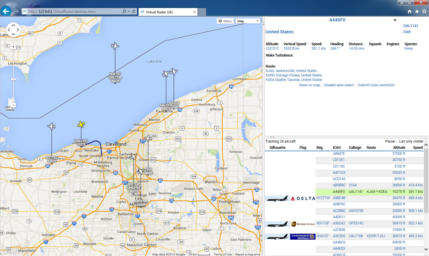
Over the Thanksgiving holiday, I saw 25 aircraft flying around Cleveland on average. I think the most I saw was 48 at once. Not all aircraft have full ADS-B implementations. For example: I would see a call sign but no position data. My receive range (depending on aircraft altitude) was east of Toledo to the PA border and south to Canton. Visit my write-up on this project: ADS-B Decoding with ADSBSharp and VirtualRadar Server.

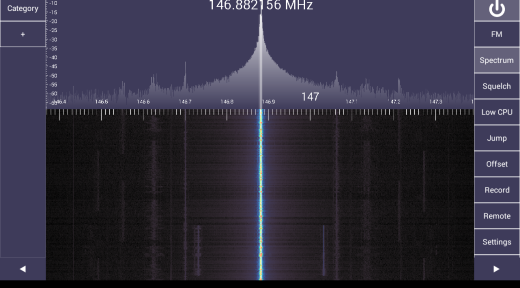
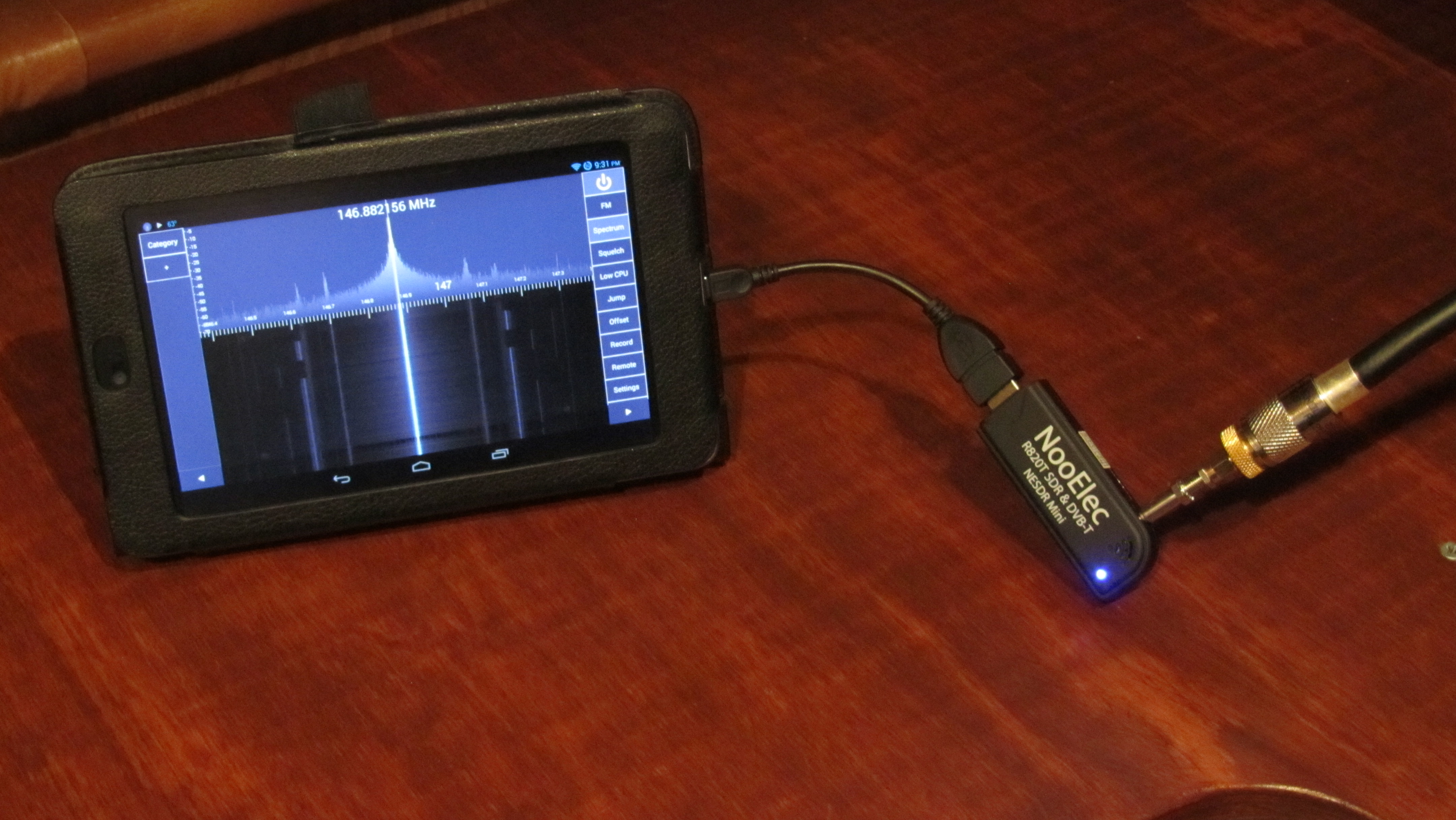
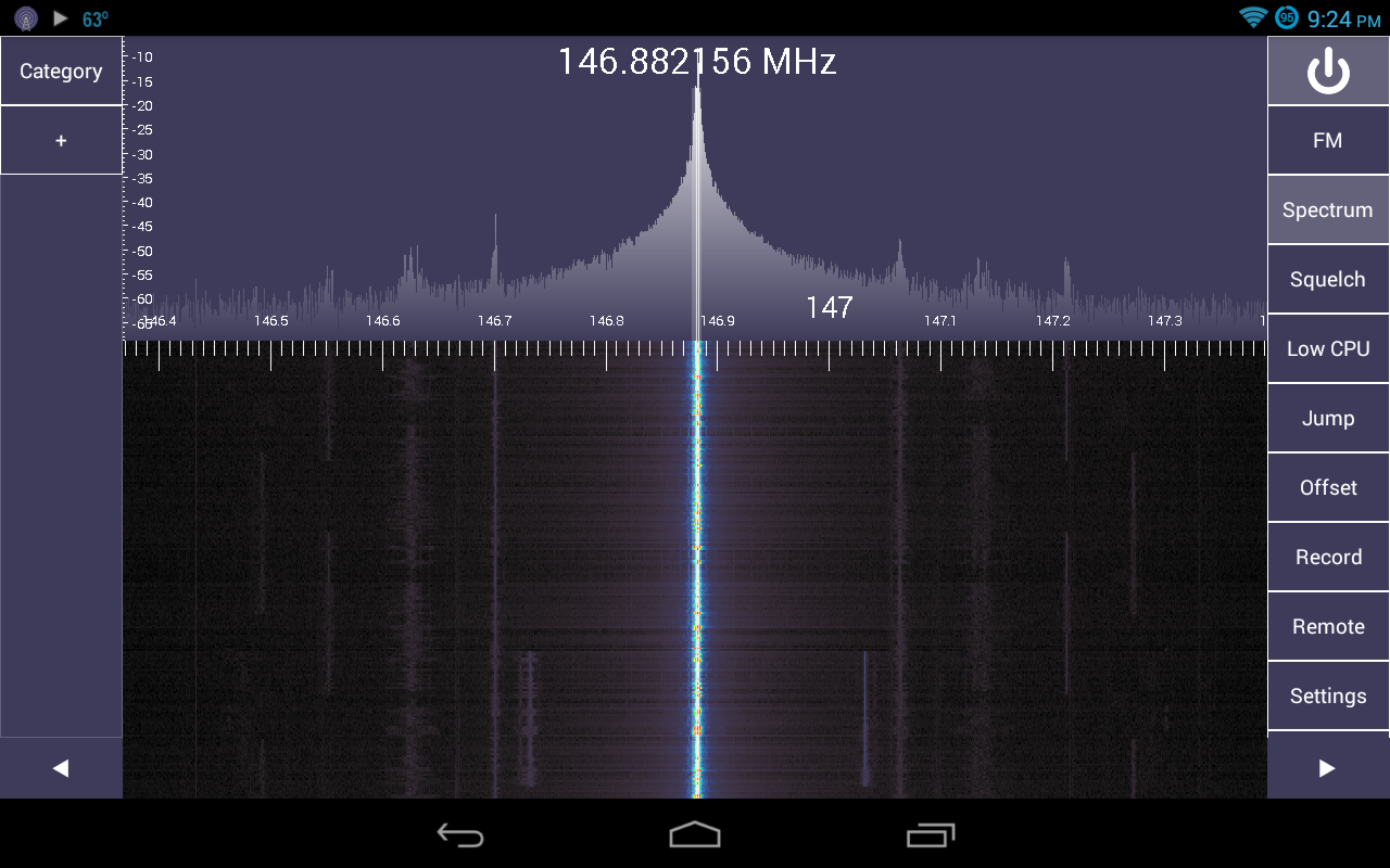
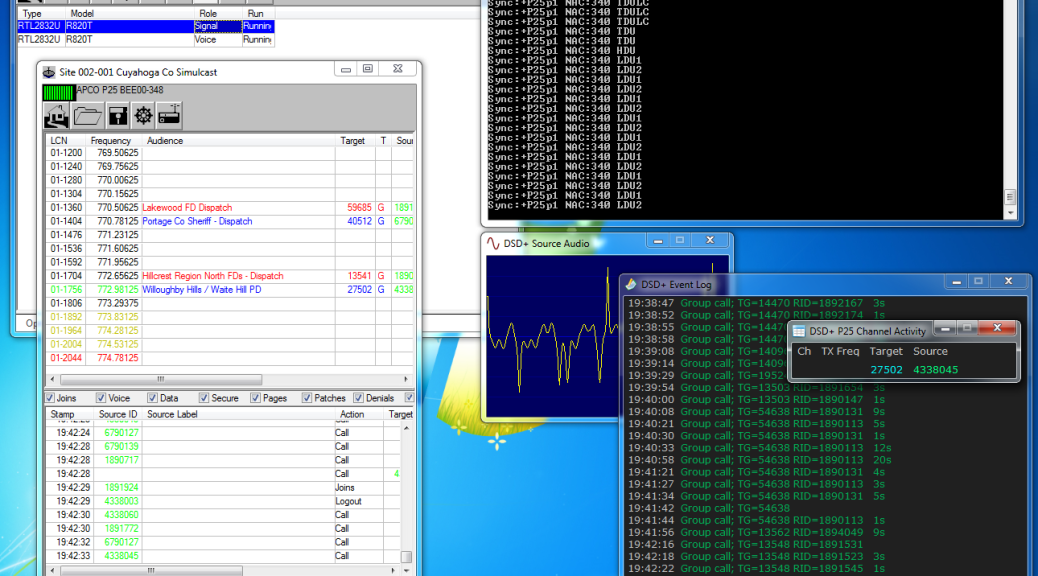
The second project is a little more complicated but it helped me understand how trunked radio systems work. With the FCC narrowbanding mandate in certain RF spectrum, many public service agencies have decided to “go digital.” In my area the MARCS-IP system and the Greater Cleveland Radio Communications Network are most popular. Both are P25 trunked digital systems. P25 is a specification for voice and data transmission. Trunked radio systems operate by having a radio send data to the control channel requesting communication on a talkgroup. The control channel directs all users of that talkgroup to a specified channel. When the user is done transmitting, all radios switch back to monitoring the control channel for further instructions. This is done seamlessly and allows many users (agencies) to use a small set of radio frequencies. Users only hear the conversations on their assigned talkgroup and not other users on the same system.

dongle-bits-06-p25_trunked_decoding-single_voice_decoder
P25 trunked decoding with a single voice decoder.

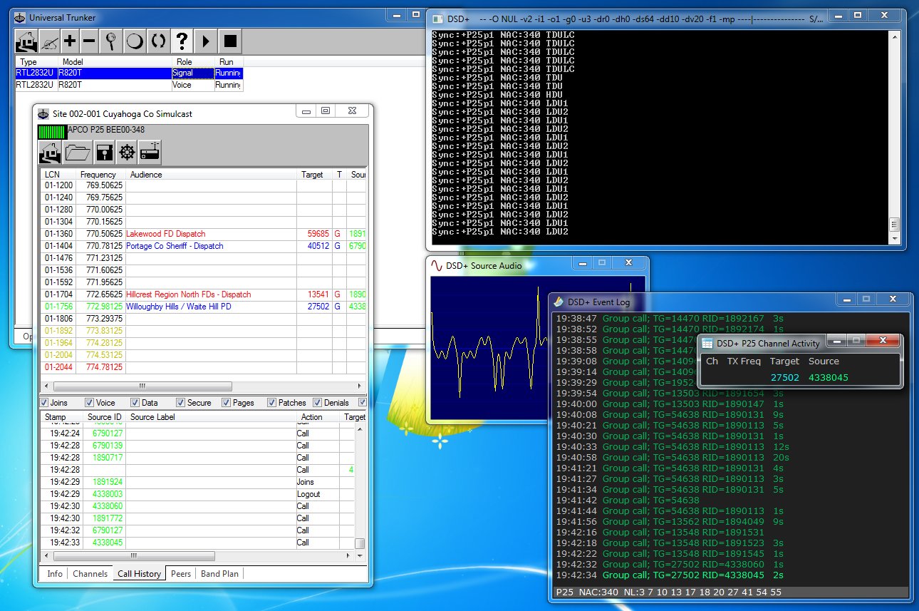
Scanners that receive these systems run $500 and go up from there. Using two RTL-SDR dongles and software (mostly free), I’ve been able to receive P25 trunked systems for about $65. One dongle monitors only the control channel and other dongle(s) jump frequencies to receive the digital voice modulation with a program decoding the audio. I can have as many voice receivers as I want whereas a scanner cannot be expanded. Most I’ve heard of is eight. There are some drawbacks like portability. Find out my experiences in my P25 Trunked Tracking post.

Fresh Baked Pi

Raspberry Pi foundation released new models over the last couple months. The biggest news coming at the beginning of February: the Raspberry Pi 2. This model comes with a quad-core CPU and 1GB RAM offering a six times speed improvement, still at $35. Initial reports are it is a lot faster!

Raspberry Pi 2

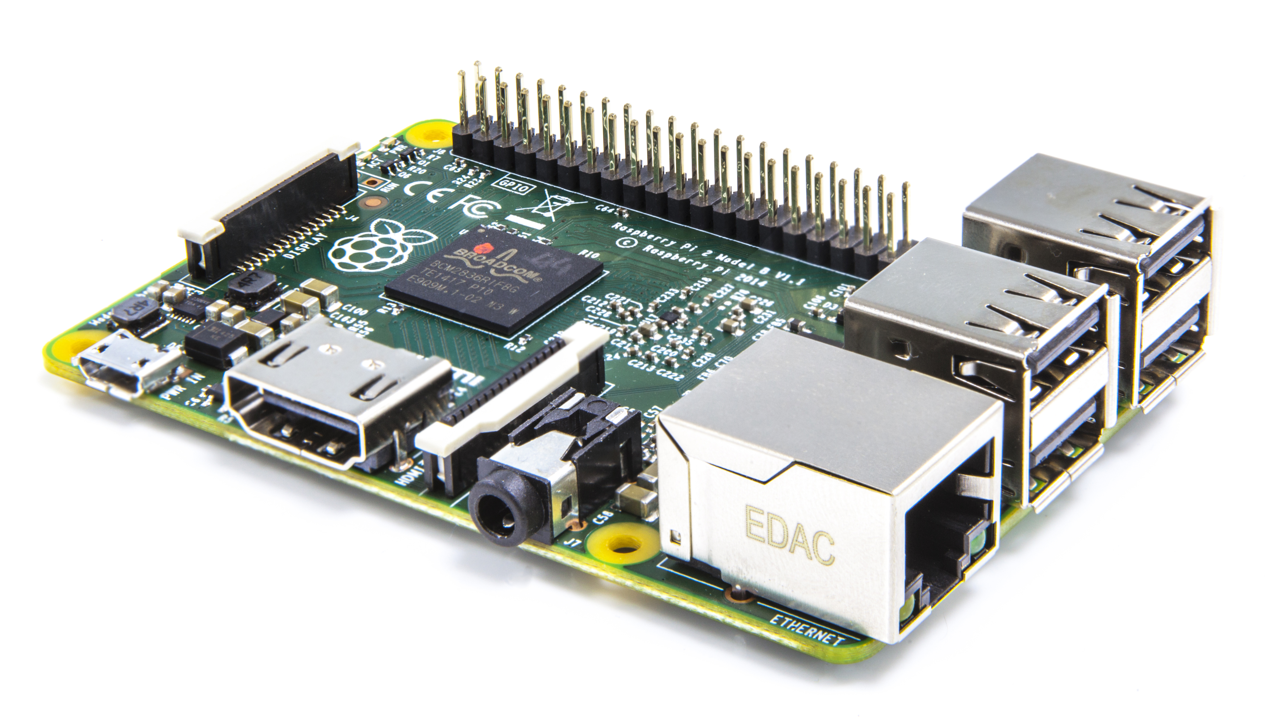
Along with the new Pi2 came a new version of the Raspbian operating system with optimizations and a new look. In the near future, Microsoft will be releasing a version of Windows 10 Embedded for the Raspberry Pi 2 FREE OF CHARGE! (see the Raspberry Pi 2 link above.)

That’s A Wrap

A goal behind this series has been to expose many hams to newer technologies and younger people to ham radio. These technologies are getting young people interested in experimenting, programming, and even Ham Radio. On podcasts I watch, I’ve heard “I want to get my Ham Radio license” by 20 and 30 year olds like I’ve never heard before. These are young people interested in experimenting, making things, building things, and hacking things — all of which are the foundation of Amateur Radio. Making has evolved into writing software, sending a chip a set of commands and analyzing what is returned, or analyzing packets. Then figuring out “what can I do with this?”

I saw a great technology round-table over the holidays and they talked about getting kids into technology. Many of the methods apply to Ham Radio. As a builder, you build something and presume what will happen. Then something different happens and now you have a mystery to solve. “Why did X happen and not Y?” A new theory develops and sucks you in. This is exactly how the Raspberry Pi, RTL-SDR, and every project surrounding them came to be. It is my opinion that we, as the Amateur Radio community, need to encourage, capitalize, and focus efforts on younger makers and hackers to get them licensed.

As this is my last planned article, I would like to take time and thank the newsletter editors for thinking this series was worth publishing and recreating all the links I included. Thank you to those who told others about this series. I got a ton of feedback and couldn’t be happier that others have found this interesting and sparked them to start experimenting. Most of all, thank you for reading.

My Experiences as a New HF Ham Radio Operator

Updated: 5/29/2018

I’ve been licensed since 1999 and upgraded to General and Extra in 2008 but I hadn’t been on the amateur HF bands very much.  When I graduated from Grad School, I bought myself and setup a new HF station.

This post is going to be about my experiences, things I’ve learned along the way, and maybe some things that may not be obvious to someone starting out.  I will add to this post.

This is not meant to be “all-inclusive” by any means and not meant to be a substitute for elmering and experience.  It’s meant to be for someone who has operated VHF/UHF for a long while but just venturing out into HF.

I’m bitter in alot of this post because many points draw on real interactions I’ve encountered.  It’s not to discourage you to operate HF but to be better than the other guy acting like a jerk.  Common sense helps tremendously.  Folks out there who are all about the points, number of exchanges, getting that last contact, and awards common sense almost always goes out the window.  Just remember you have a choice to not work those stations.

A quick note… ac6v.com has a TON of good information on everything from “antennas to zones.”  I think it could be organized a little better and layout is a little 1996ish, regardless 700 amateur radio topics are covered. The Google search at the top really helps finding things.

Let’s get started.

SSTV Transmissions from the International Space Station – December 2014 edition

I saw a news story on the ARRL website that talked about the Russian International Space Station cosmonauts plan to send Slow Scan TV images around the holidays.  December 18 and December 20, 2014.  Those are two of my interests, SSTV (or digital modes in general) and spaceflight.  From the news story:

The Russian Amateur Radio on the International Space Station (ARISS) team members plan to activate slow-scan television (SSTV) from the ISS on December 18 and December 20. The expected SSTV mode will be PD180 on a frequency of 145.800 MHz with 3-minute off periods between transmissions.

I setup my station to monitor 145.800 MHz on both days to see if I could receive any images, I did!

Station setup: MP Antennas Classic Mobile NMO Antenna – This is a local company in Cleveland and were reviewed in QST.  Been using their antennas for a long time with great success.  Since the antenna is multi-polarized (the MP in the company name), it is supposed to be a good substitution for receiving satellite transmissions without a directional antenna and not worrying about Doppler Shift (which needs to be accounted for in some cases).  The height is about 15 feet.

The antenna was connected to my ICOM IC-7000 with DSP settings turned off on 145.800 MHz FM.  Used this radio only because my SignaLink USB is connected to it and the one I use for digital operation on all bands.  MMSSTV is the Slow-Scan TV program I use.

I have tutorials available to help get your station setup and getting started with MMSSTV to receive images from the ISS.

I received 6 images total including 2 partial images from my location near Cleveland (EN91bl) as the ISS was flying overhead.

SSTV Transmissions from the International Space Station 2014-12-18 1901
2014-12-18 1901 UTC
SSTV Transmissions from the International Space Station 2014-12-18 2037
2014-12-18 2037 UTC
SSTV Transmissions from the International Space Station 2014-12-18 2214
2014-12-18 2214 UTC
SSTV Transmissions from the International Space Station 2014-12-20 1719
2014-12-20 1719 UTC
SSTV Transmissions from the International Space Station 2014-12-20 1854
2014-12-20 1854 UTC
SSTV Transmissions from the International Space Station 2014-12-20 2029
2014-12-20 2029 UTC

Dongle Bits: Settings, Programs, & Apps for Software Defined Radio

This article appeared in the The Lake Erie Amateur Radio Association newsletter The Spirit of ’76 and ’88 October 2014 edition and The Wood County Amateur Radio Club newsletter CQ Chatter November 2014 edition.

Read the rest of the series in the Dongle Bits articles category.


Last time on Dongle Bits, I talked about the $20 European TV tuner dongle that was hacked allowing direct access to the signal data. The result is a cheap wideband receiver for your computer. We’re going to take a look at key settings you should know about when using these devices. Then look at some software and projects that transform these into systems that would have cost hundreds or thousands of dollars!

PPM and Settings

An important thing to know about these dongles: they are cheaply made and not tested for accuracy. They are designed to receive DVB-T signals at a bandwidth of 6 – 8 MHz where a few KHz error doesn’t matter. This is obviously not true when you’re dealing with FM signals that are 16 KHz wide or digital at 12.5 where a few KHz will put you on a completely different frequency or channel.

PPM stands for parts per million and is the difference in received frequency vs. frequency shown. To visualize this, use SDRSharp to receive a known FM signal. The center frequency shown will be different from the signal on the scope. Typical PPM offset is anywhere from 45 – 65 and will be in the programs settings. The dongle will drift another 2 – 5 PPM over the next 20 – 45 minutes as it warms up. Gain is obviously another setting that will help you receive signals. The RTL AGC setting works but will err on the side of too much gain. Manually, using more than 32.8 dB will overload and produce duplicate signal spikes. The Correct IQ setting will get rid of phantom spikes at lower gain settings.

PPM at 0
Dongle with no frequency correction. The actual 162.550 frequency is just to the left of the displayed frequency. 162.550 is one of the NOAA Weather Radio frequencies.
RTL-SDR Settings (PPM corrected)
Shows the gain and PPM frequency correction of 55 for the dongle I’m using.
PPM Corrected
Shows 162.550 centered with frequency correction applied.

The crystals on the RTL-SDR dongle can be replaced with higher accuracy temperature controlled crystals (TCXO) that have a variance of 1 ppm! These crystals are $10 but you have to wait for them to ship from China. Pre-modified dongles are available but you will pay three times the price for the dongle.

Android

PCs aren’t the only place these SDRs can be used. They can be plugged into an Android device too. You will need a USB OTG cable (on-the-go) and Android 3.1 or later. Search Amazon or EBay for “USB OTG.” OTG is a standard for plugging in USB keyboards, mice, and thumb drives into mobile devices. Running external USB devices off the internal battery will drain it much faster. A powered USB hub would off-load the dongle power consumption. Apps include SDR Touch (wideband receiver program), ADSB Receiver, and SDRWeather for monitoring NOAA weather alerts on your device.

IMG_0003
This is the RTL-SDR running on my Android Nexus 7 tablet with SDR Touch receiving the 146.880 repeater in Lakewood, Ohio. It is connected with a USB OTG cable to the RTL-SDR dongle, then to an MCX to SMA, and then SMA to PL259 adapter.
Screenshot_2014-09-25-21-24-12
This is a screenshot of the above setup with SDR Touch.

What can I do with this thing?

The definitive source on all things RTL-SDR is at the appropriately named www.rtl-sdr.com website. This site has it all. They regularly post software, updates, projects, and new developments. There is something new just about every week.

Some features of RTL-STR.com are The Big List Of RTL-SDR Supported Software. This is the list of software packages that support RTL-SDR on all platforms. Software ranges from wideband receivers to single purpose programs. This will give you some ideas of things to try with RTL-SDR. SDRSharp was written to have plugins extend the functionality of the program. These include plugins that make SDRSharp scan frequencies, add an audio FFT, scope, level meter, or CTCSS (PL) detector.

There is an extensive list of projects and write-ups including an Amateur Radio category. Some interesting ones are receiving live NOAA satellite imagery, analyze cellular phone GSM signals, radio astronomy, signal strength heat mapping (foxhunting?), and how Brazil uses our military satellites to transmit SSTV images.

With the onset of many digital standards and narrowbanding, there are more digital signals out there you may not be able to identify by hearing them or seeing them on the waterfall. This Signal Identification Guide has known types, frequencies they may be heard on, mode, bandwidth, sample audio, and waterfall image. I find myself using the Radio Reference database search utilities to help identify signals and their owners (a premium account maybe needed for some features).

My first SDR project was to use the Raspberry Pi as a SDR remote network server. The Raspberry Pi could be placed in an attic or basement connected to an antenna and controlled by another computer.

Audio can be piped from one program into another using Virtual Audio Cable (VAC). Some time ago, during one of the digital nets on the .76 repeater in Cleveland, I used SDRSharp and VAC to receive the FLDIGI messages being passed on the net. The signal path looked like this: received RF signal (146.760) -> RTL-SDR (signal data) -> SDRSharp (audio out) -> Virtual Audio Cable -> FLDIGI (audio in) -> message decoded on screen. If I had a HackRF, I probably would have been able to transmit messages without using any “ham” gear.

The next and probably final article, I will demonstrate tracking airplanes equipped with ADS-B transmitters and listening to trunked P25 public service radio systems for under $100.