This article appeared in the The Lake Erie Amateur Radio Association newsletter The Spirit of ’76 and ’88 October 2014 edition and The Wood County Amateur Radio Club newsletter CQ Chatter November 2014 edition.
Read the rest of the series in the Dongle Bits articles category.
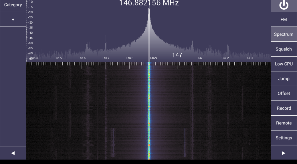
Last time on Dongle Bits, I talked about the $20 European TV tuner dongle that was hacked allowing direct access to the signal data. The result is a cheap wideband receiver for your computer. We’re going to take a look at key settings you should know about when using these devices. Then look at some software and projects that transform these into systems that would have cost hundreds or thousands of dollars!
PPM and Settings
An important thing to know about these dongles: they are cheaply made and not tested for accuracy. They are designed to receive DVB-T signals at a bandwidth of 6 – 8 MHz where a few KHz error doesn’t matter. This is obviously not true when you’re dealing with FM signals that are 16 KHz wide or digital at 12.5 where a few KHz will put you on a completely different frequency or channel.
PPM stands for parts per million and is the difference in received frequency vs. frequency shown. To visualize this, use SDRSharp to receive a known FM signal. The center frequency shown will be different from the signal on the scope. Typical PPM offset is anywhere from 45 – 65 and will be in the programs settings. The dongle will drift another 2 – 5 PPM over the next 20 – 45 minutes as it warms up. Gain is obviously another setting that will help you receive signals. The RTL AGC setting works but will err on the side of too much gain. Manually, using more than 32.8 dB will overload and produce duplicate signal spikes. The Correct IQ setting will get rid of phantom spikes at lower gain settings.
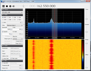
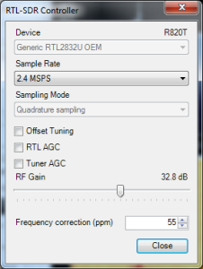
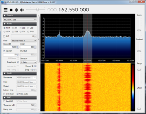
The crystals on the RTL-SDR dongle can be replaced with higher accuracy temperature controlled crystals (TCXO) that have a variance of 1 ppm! These crystals are $10 but you have to wait for them to ship from China. Pre-modified dongles are available but you will pay three times the price for the dongle.
Android
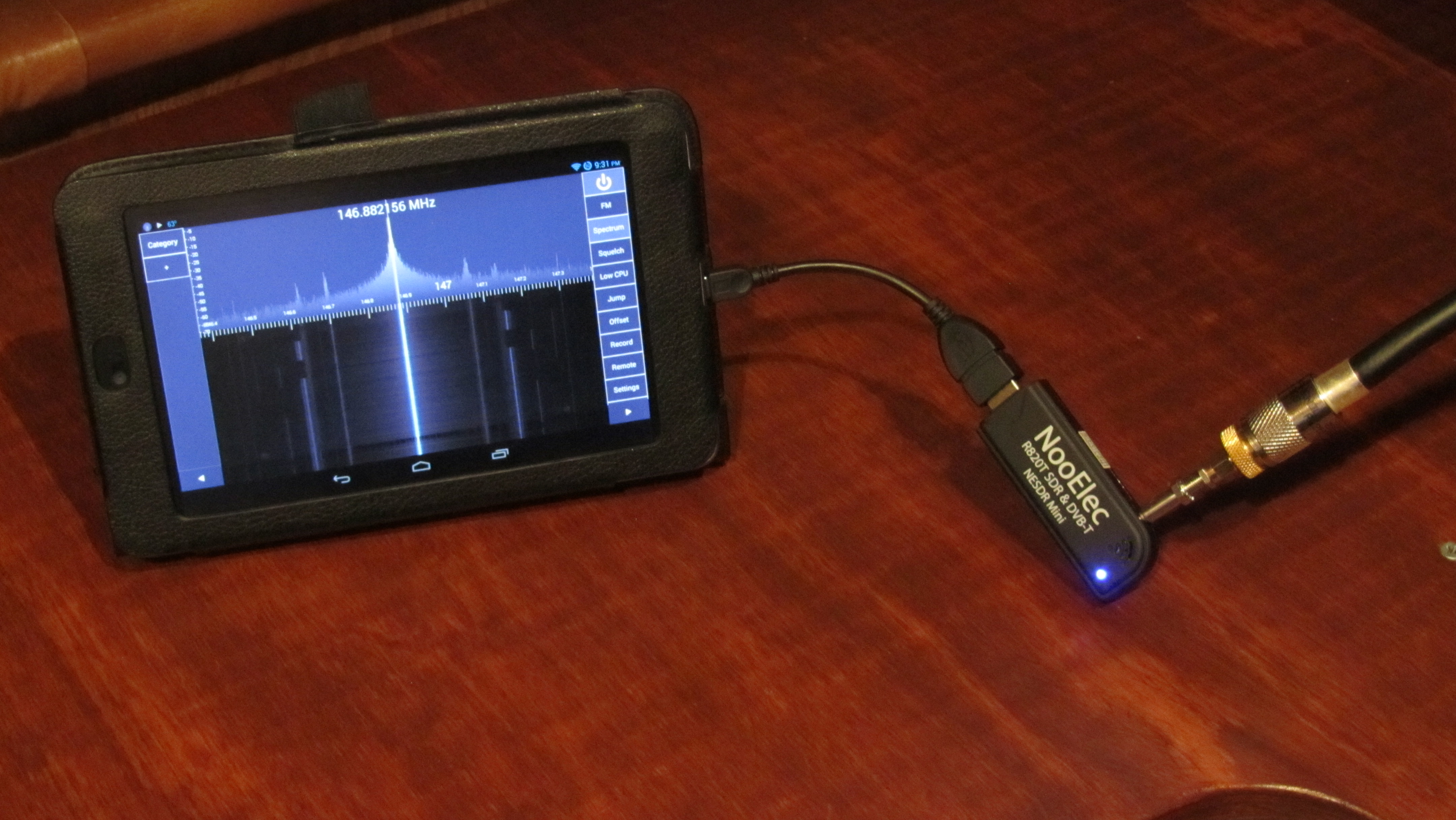
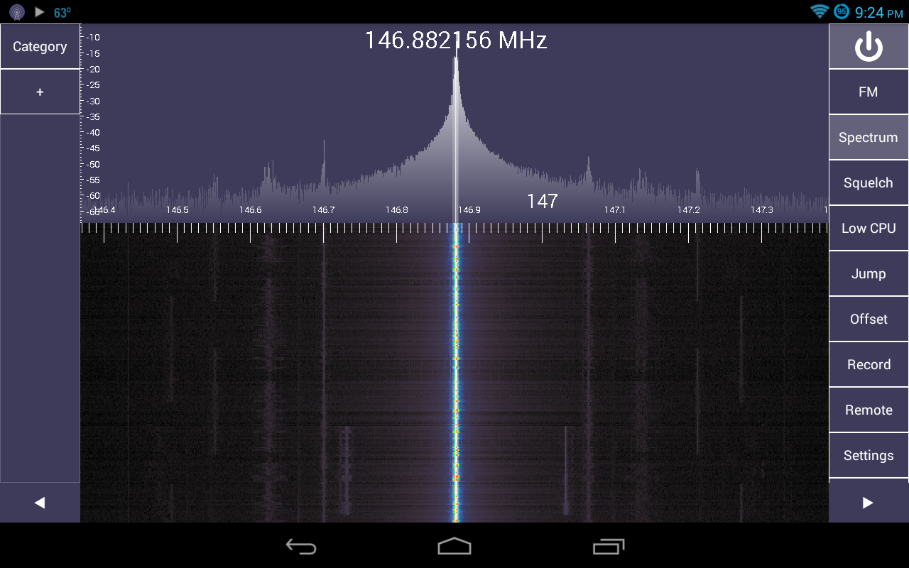
PCs aren’t the only place these SDRs can be used. They can be plugged into an Android device too. You will need a USB OTG cable (on-the-go) and Android 3.1 or later. Search Amazon or EBay for “USB OTG.” OTG is a standard for plugging in USB keyboards, mice, and thumb drives into mobile devices. Running external USB devices off the internal battery will drain it much faster. A powered USB hub would off-load the dongle power consumption. Apps include SDR Touch (wideband receiver program), ADSB Receiver, and SDRWeather for monitoring NOAA weather alerts on your device.
What can I do with this thing?
The definitive source on all things RTL-SDR is at the appropriately named www.rtl-sdr.com website. This site has it all. They regularly post software, updates, projects, and new developments. There is something new just about every week.
Some features of RTL-STR.com are The Big List Of RTL-SDR Supported Software. This is the list of software packages that support RTL-SDR on all platforms. Software ranges from wideband receivers to single purpose programs. This will give you some ideas of things to try with RTL-SDR. SDRSharp was written to have plugins extend the functionality of the program. These include plugins that make SDRSharp scan frequencies, add an audio FFT, scope, level meter, or CTCSS (PL) detector.
There is an extensive list of projects and write-ups including an Amateur Radio category. Some interesting ones are receiving live NOAA satellite imagery, analyze cellular phone GSM signals, radio astronomy, signal strength heat mapping (foxhunting?), and how Brazil uses our military satellites to transmit SSTV images.
With the onset of many digital standards and narrowbanding, there are more digital signals out there you may not be able to identify by hearing them or seeing them on the waterfall. This Signal Identification Guide has known types, frequencies they may be heard on, mode, bandwidth, sample audio, and waterfall image. I find myself using the Radio Reference database search utilities to help identify signals and their owners (a premium account maybe needed for some features).
My first SDR project was to use the Raspberry Pi as a SDR remote network server. The Raspberry Pi could be placed in an attic or basement connected to an antenna and controlled by another computer.
Audio can be piped from one program into another using Virtual Audio Cable (VAC). Some time ago, during one of the digital nets on the .76 repeater in Cleveland, I used SDRSharp and VAC to receive the FLDIGI messages being passed on the net. The signal path looked like this: received RF signal (146.760) -> RTL-SDR (signal data) -> SDRSharp (audio out) -> Virtual Audio Cable -> FLDIGI (audio in) -> message decoded on screen. If I had a HackRF, I probably would have been able to transmit messages without using any “ham” gear.
The next and probably final article, I will demonstrate tracking airplanes equipped with ADS-B transmitters and listening to trunked P25 public service radio systems for under $100.
